![Azure Enterprise Integration Series – Part 3]()
by Daniel probert | Mar 8, 2017 | BizTalk Community Blogs via Syndication
Azure Enterprise Integration Series
Part 3: Visual Studio and Project Types
1. Visual Studio Development
As an enterprise integration developer, Azure gives you some new choices. Foremost amongst those is the ability to develop code *outside of Visual Studio*. Whilst that is the norm for most open-source and non-Microsoft technologies (e.g. Python, Ruby, anything developed on a non-Windows PC), for most Microsoft integration developers, developing outside of Visual Studio may take you outside of your comfort zone.
In fact, when Logic Apps first debuted, much was made of the fact that you could develop in your browser – a revolutionary idea (to Microsoft developers) and one that Microsoft have put a lot of time and effort into.
In fact, the early versions of Visual Studio Online were focused around you being able to write. Test, and deploy C# code from your browser, the legacy of which still carries on with Azure Functions today.
But developing in a browser introduces its own concerns: how you do manage your code, how do you source control it, what about promoting it to different environments, etc.
Some organisations love the idea of browser development: these are organisations that have jumped whole-heartedly on the Agile bandwagon, use Git and Scrum, release regularly, and much prefer a lighter-weight development process.
But for most Enterprises, Visual Studio is where it’s at: it complements our existing development processes; reduces training on new development techniques; and is familiar to most of the developers we employ.
2. Project Types
Although Visual Studio contains templates for many different types of projects, we’re only interested in a subset of them for Azure integration development:
|
Visual Studio Project Type
|
Supported Azure Resources
|
|
Azure Resource Group
|
API Connection
App Service
Azure SQL Server1
Integration Account2
Logic Apps3
Service Bus
Storage Account
etc.
|
|
Azure Functions
|
Functions
|
|
ASP.NET Web Application
|
Web App4
Mobile App4
API App4
|
|
Integration
|
Integration Account contents (schemas etc.) 3
|
|
Web Job
|
Web Job
|
|
SQL Server Database
|
Database objects (tables etc.) 2
|
There are a few discrepancies with the project types though:
1 An Azure SQL Server is defined in an ARM template, although the SQL entities (databases, tables, stored procedures, etc.) need to be defined in a separate SQL Server Database project.
2 At the current time, the Integration project type doesn’t support the creation of the actual Integration Account in Azure, so you need a separate Azure Resource Group project that contains the ARM Template for the Integration Account.
3 Although Logic Apps are created in an Azure Resource Group project, they have their own designer. They are the only resource in an Azure Resource Group project that has a dedicated designer.
4 The ASP.Net Web Application project type contains the code for web applications, but doesn’t define the App Service or App Service Plan (ASP): you need a separate ARM Template for this. Although you can create the App Service/ASP at the time you publish from Visual Studio, this doesn’t allow you put the definition for the App Service/ASP in source control.
Most of the project types we use for integration development can be found in the cloud category:
The rest of this section covers the individual project types.
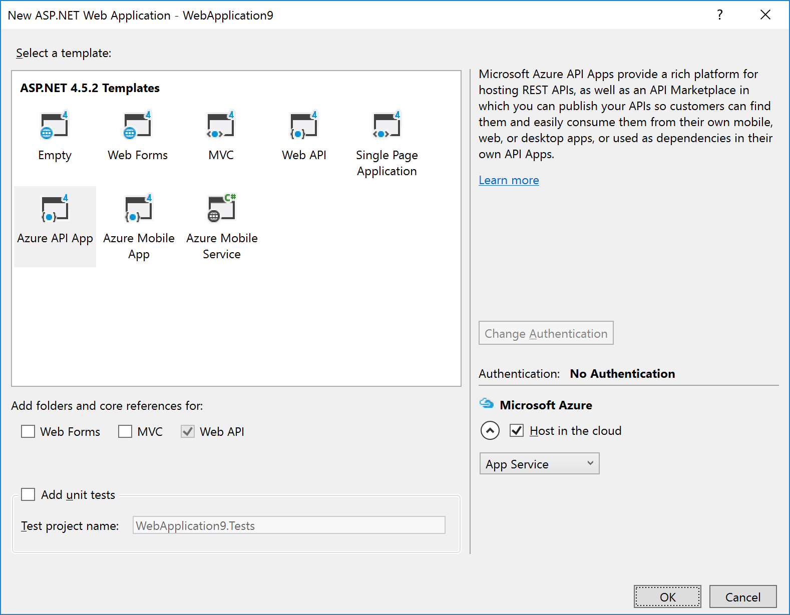
2.1 ASP.NET Web Application Project
The ASP.NET Web Application project template covers most Azure App Service technologies (Web Apps, API Apps, Mobile Apps).
After selecting this option (and entering the project/solution name details), you are given a dialog where you can select the type of ASP.NET technology, and whether you want to host in in Azure:
|
Note: If you’re using the Visual Studio testing framework, we suggest you select the option to Add unit tests in the above dialog – this will create a separate Unit Tests project with an example of a unit test.
|
The example in the image above shows that we wish to create an Azure API App and to host it in Azure.
Selecting the Host in the cloud option will cause a secondary dialog to appear, which is used to create an App Service and create/select an App Service Plan (this is the same dialog used when you choose the Publish option):
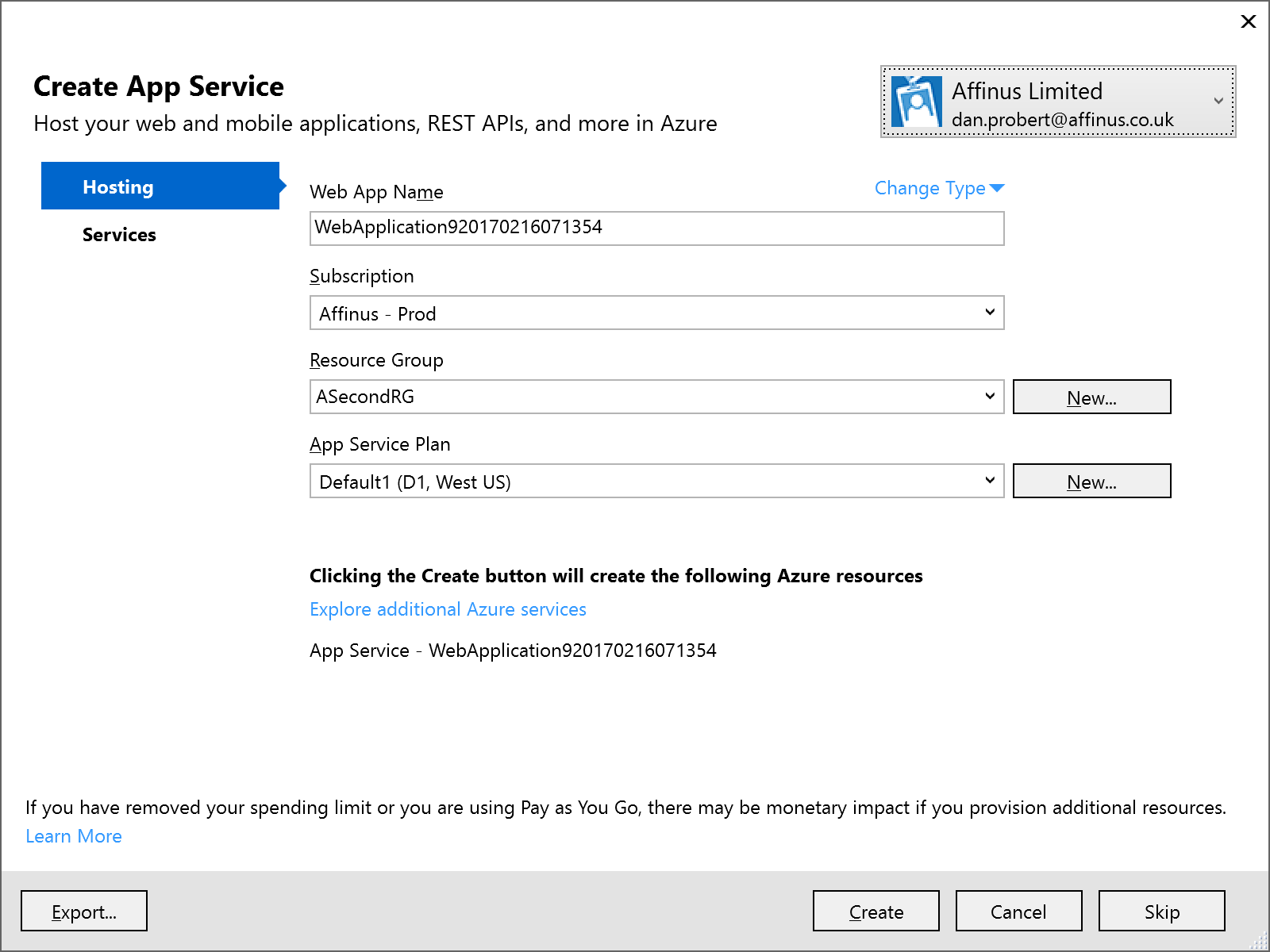
Remember: An App Service is equivalent to an IIS Application, and the App Service Plan defines the type of Server Farm your application is hosted on (i.e. how many servers, types of servers, how much memory you have, etc.).
We recommend that you *don’t* select the option to host in Azure at project creation: the rationale behind this is that you still must supply the same information in an ARM template (i.e. the App Service and App Service Plan) to deploy the App Service (and your ASP.NET application) from VSTS.
|
Note: Although Visual Studio can create an App Service/App Service Plan for this app (via the Publish option), we recommend creating a separate Azure Resource Group project in Visual Studio that contains an App Service and App Service Plan for this ASP.NET Web Application project. This Resource Group Project can then be deployed from both Visual Studio and VSTS.
|
|
Note: One thing that the above dialog is useful for, is creating an ARM Template that specifies your App Service and App Service Plan: if you fill in the dialogue, and then click the Export… button, it will save an ARM Template file that you can use in an Azure Resource Group project, and you can then cancel out of the dialog.
|
2.2 API App Project
API Apps are a type of ASP.NET Web Application project, and are created by selecting that option under Cloud projects. The API App template is then selected:
The API App template in Visual Studio creates a stubbed MVC REST app, with a Swagger interface:
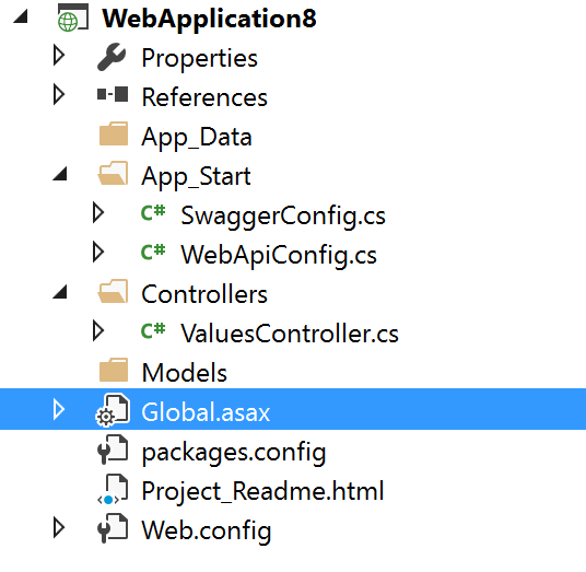
The developer then modifies this stub to implement the required functionality: the actual REST methods are contained in the ValuesController.cs file.
|
Note: Although Visual Studio can create an App Service/App Service Plan for this app (via the Publish option), we recommend creating a separate Azure Resource Group project in Visual Studio that contains an App Service and App Service Plan for this ASP.NET Web Application project. This Resource Group Project can then be deployed from both Visual Studio and VSTS.
|
2.3 Azure Functions Project
An Azure Functions project is a specialization of an ASP.NET Web Application project: Functions are hosted in a Function App, which is a specialized version of an App Service (technically, Functions are a type of Web Job, which is a type of App Service). Function Apps also use an App Service Plan: A Function App can use a standard App Service Plan (which limits the number of executions, but is charged at a regular monthly amount); or it can use a dynamic App Service Plan (known as consumption billing), where you pay per execution. The Azure Functions project in Visual Studio represents the Function App that needs to exist in Azure.
|
Note: Functions can also be authored in the portal, but this is not recommended as any changes are not automatically reflected in Source Control in VSTS.
|
The Azure Functions project template is (as of this writing) in preview – therefore its capabilities (and its location) may change in future.
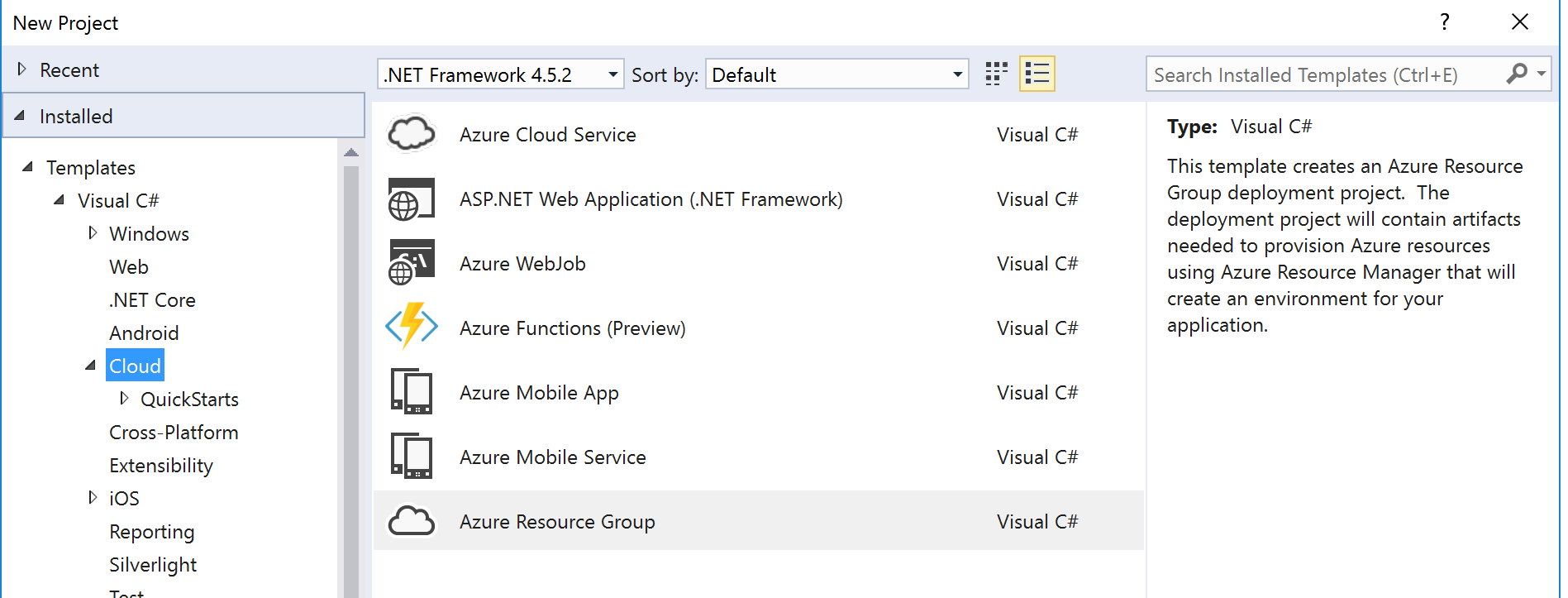
To create an Azure Functions project, select the template from the New Project screen:
This will create a stub Function App project that looks like this:
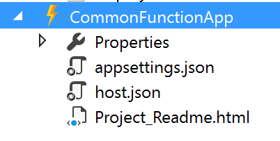
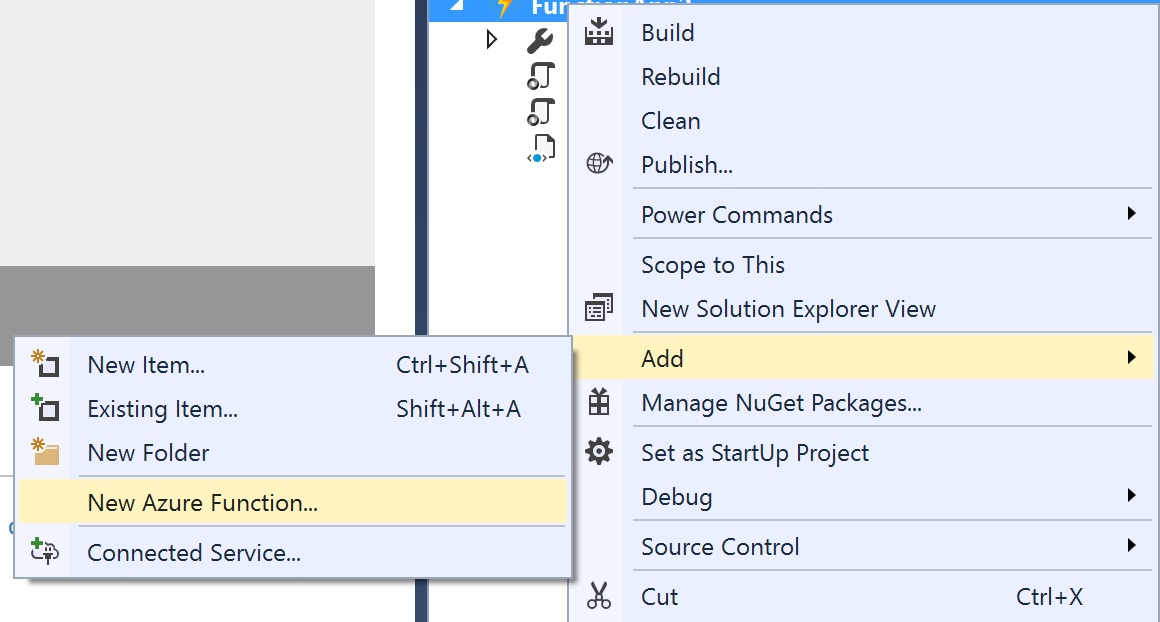
An Azure Functions project can contain one or more functions – each function will be in a separate folder in the project. When the project is first created, it will contain no functions – functions can be added by the “Add” option in the project:
The New Azure Function dialog allows you to select the type of function to create:
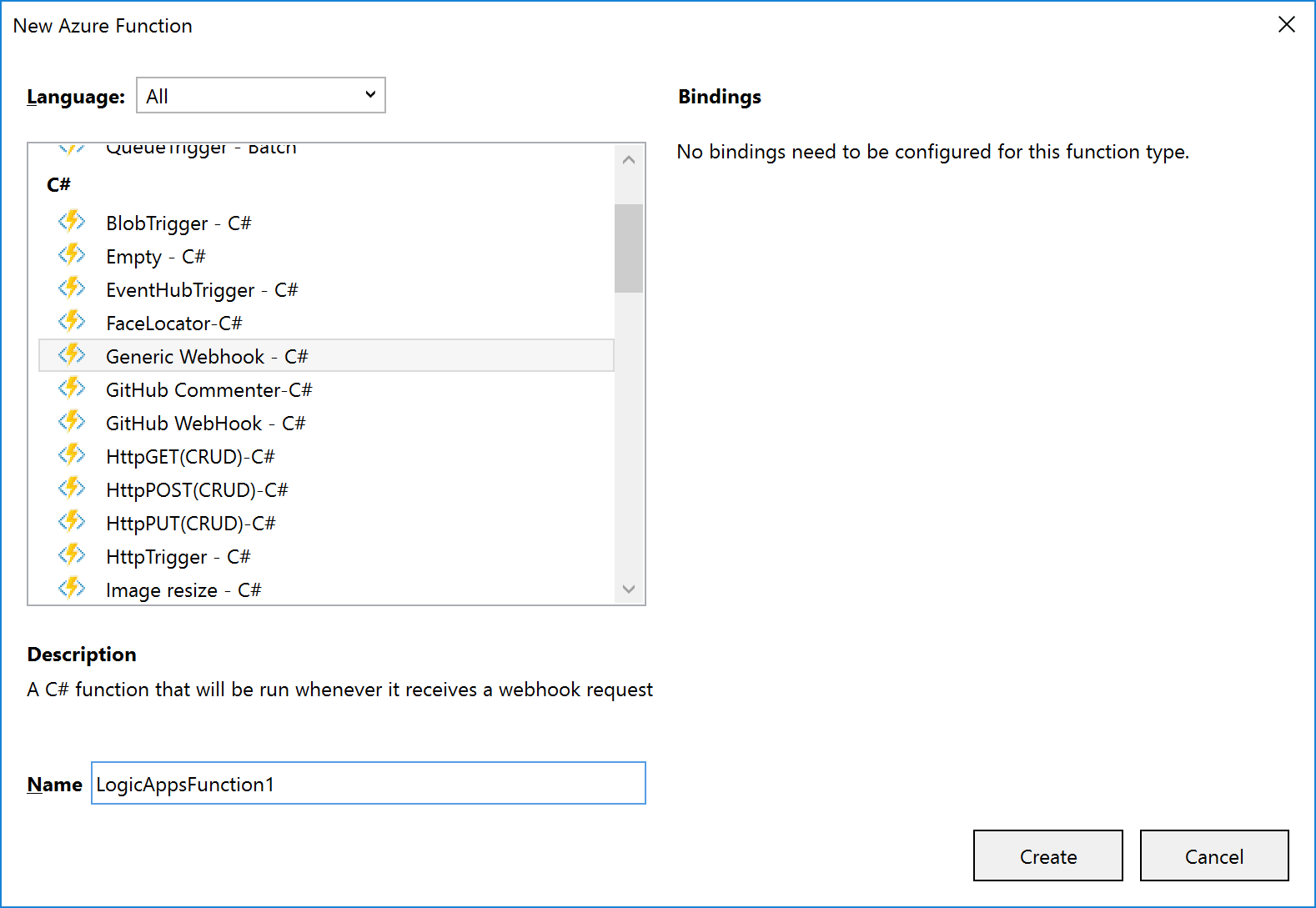
A function will consist of several files, depending on the template chosen. The example shown (and discussed) below is for a C# Generic Webhook function:
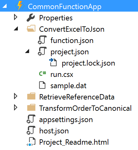
The function and function app files shown are:
|
File Name
|
Level
|
Description
|
|
function.json
|
Function
|
Contain settings for the function e.g. type of trigger, type of output, whether it starts disabled etc. For Logic App functions, you shouldn’t need to edit this, if a Generic WebHook template was used.
|
|
project.json
|
Function
|
Contains a list of dependencies this function needs from NuGet (or locally).
|
|
run.csx
|
Function
|
Contains the source code for the function.
|
|
sample.dat
|
Function
|
Contains sample data that works with the sample code in run.csx.
|
|
appsettings.json
|
Function App
|
Contains settings that affect the Function App App Service.
|
|
host.json
|
Function App
|
Contains information about the host used with the App Service.
|
|
Project_Readme.html
|
Function App
|
Read Me file, is displayed by Visual Studio when an Azure Functions project is first created.
|
|
Note: support is being added to functions for ability to use code from a pre-compiled assembly; and additionally, to have a parent function that can look at a request and forward it to a child function (function proxy). Neither of these features are available in Visual Studio now, but moving forward it will make sense to have a separate C# Library project that contains classes with the function code in them: this will allow for easier unit testing and editing.
|
|
Note: Although an Azure Functions project has a Publish option, the Function App it deploys is broken, and not visible from Logic Apps. For this reason, we recommend creating a separate Azure Resource Group project in Visual Studio that contains an App Service and App Service Plan for the Function App.
|
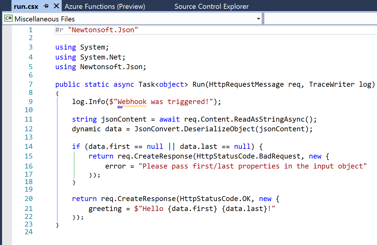
The default run.csx file for a C# Generic Webhook project looks like this:
2.4 Azure Resource Group Project
The Azure Resource Group project type lets you manage resources specified via ARM Templates.
When you create an Azure Resource Group project, you can choose to start from a number of pre-populated ARM Templates (including QuickStart templates from GitHub), or from a blank ARM Template:
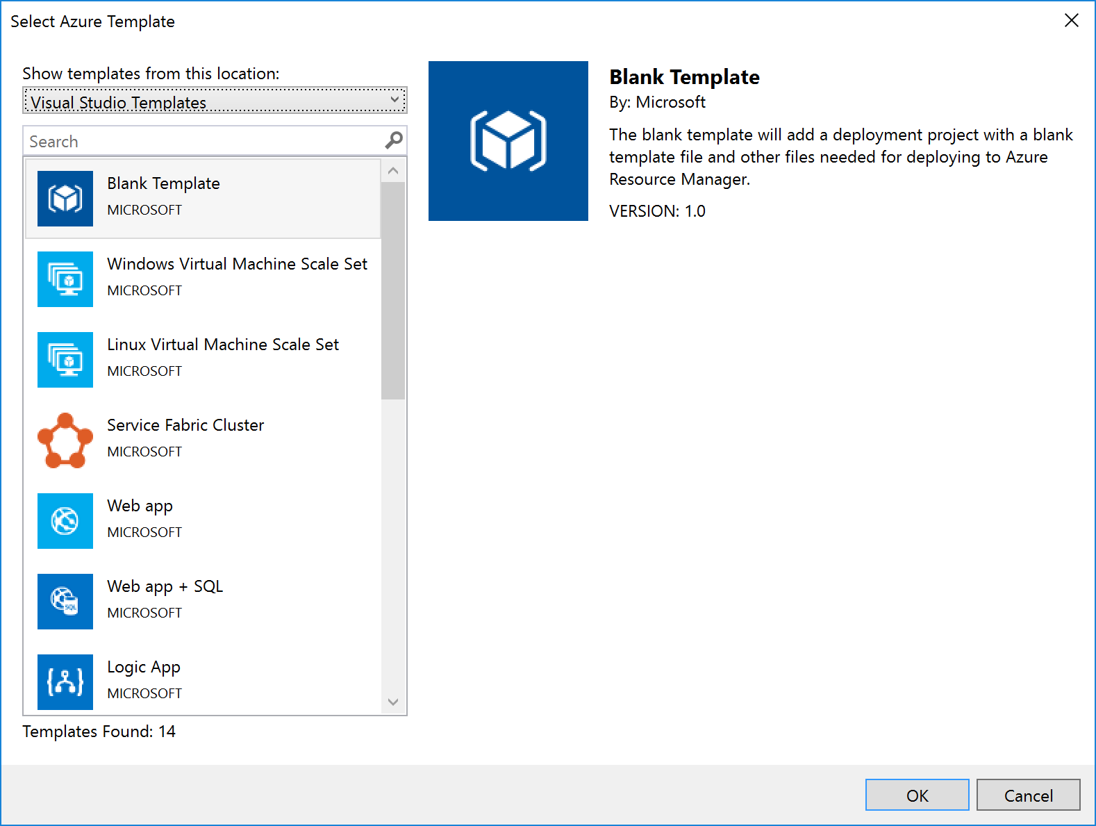
Notice that Logic Apps are one of the items in the list – if you select this option, you get a stub Logic App (i.e. something that the Logic App designer recognises as a Logic App and which it can open). Note that this assumes you have installed the Logic App tooling for Visual Studio.
|
Note: The link to download the Logic App visual studio extension can be found at the end of this article.
|
For some resources, e.g. Service Bus Namespaces, Storage Accounts, API Connections, etc., there is no template: you must start with a blank ARM Template file and add the content yourself.
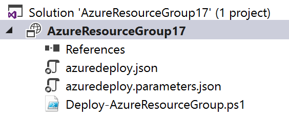
No matter which template you select, you’ll end up with a project with 3 files in it:
|
File Name
|
What
|
Description
|
|
azuredeploy.json
|
An ARM Template
|
A JSON file that describes what should be created.
|
|
azuredeploy.parameters.json
|
An ARM Template parameters file
|
A JSON file which contains values passed in to the ARM template.
Note: although only one of these is created, the idea is to create multiple template files, one for each environment.
|
|
Deploy-AzureResourceGroup.ps1
|
A Deployment PowerShell script
|
Contains a default script that creates the Resource Group and then deploys the ARM Template. This is the script that Visual Studio executes when you select the Deploy option for the project. Changing the name of this file will break the ability to deploy this project from Visual Studio.
|
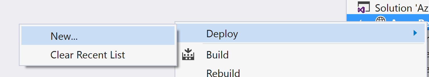
When you right-click the project file and select Deploy, you’re given the option of selecting an existing deployment, or creating a new one. All this does is pre-populate the name of the ARM Template file to use, the Parameter file to use, and the subscription being used:
Creating a new deployment prompts us to select the Subscription, Resource Group, ARM Template, Parameters File, and also allows us to edit the parameter values:
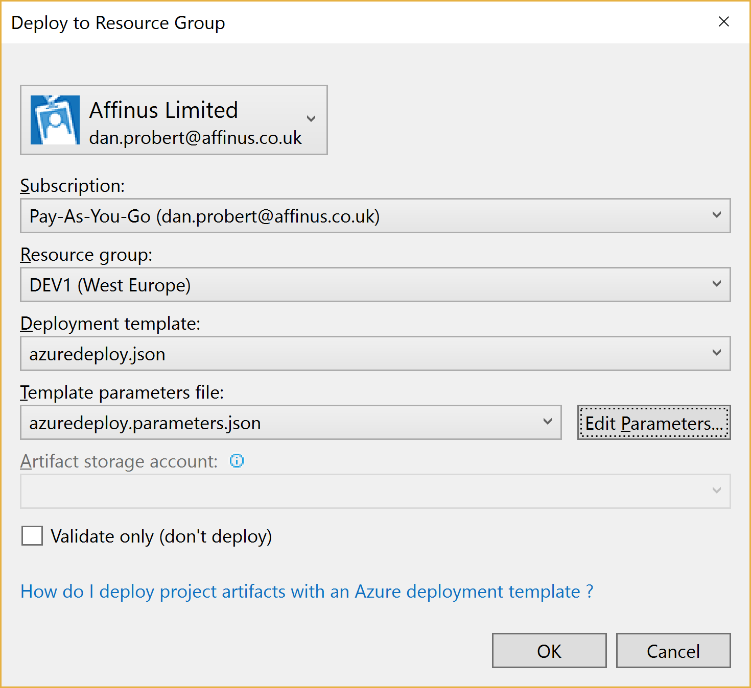
When we kick off a deployment, all that happens is that Visual Studio executes the Deploy-AzureResourceGroup.ps1 using the values supplied above.
For this reason, it is important that you don’t edit the Deploy-AzureResourceGroup.ps1 file unless you are extending the deployment in some fashion.
2.5 Integration Account Project
An Integration Account project type is used to create and store XSD Schemas and Transforms used with Azure Integration Accounts.
It is created via this option:
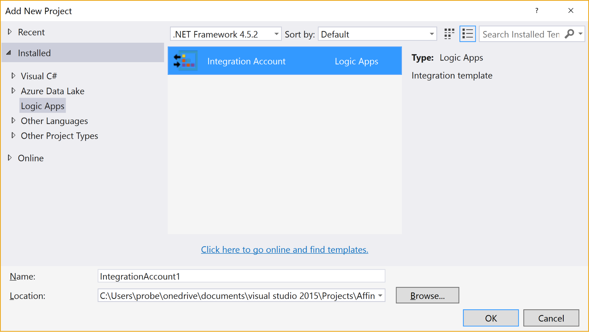
When the project is created, it has no resources in it.
Selecting the “Add New Item” gives 3 options:
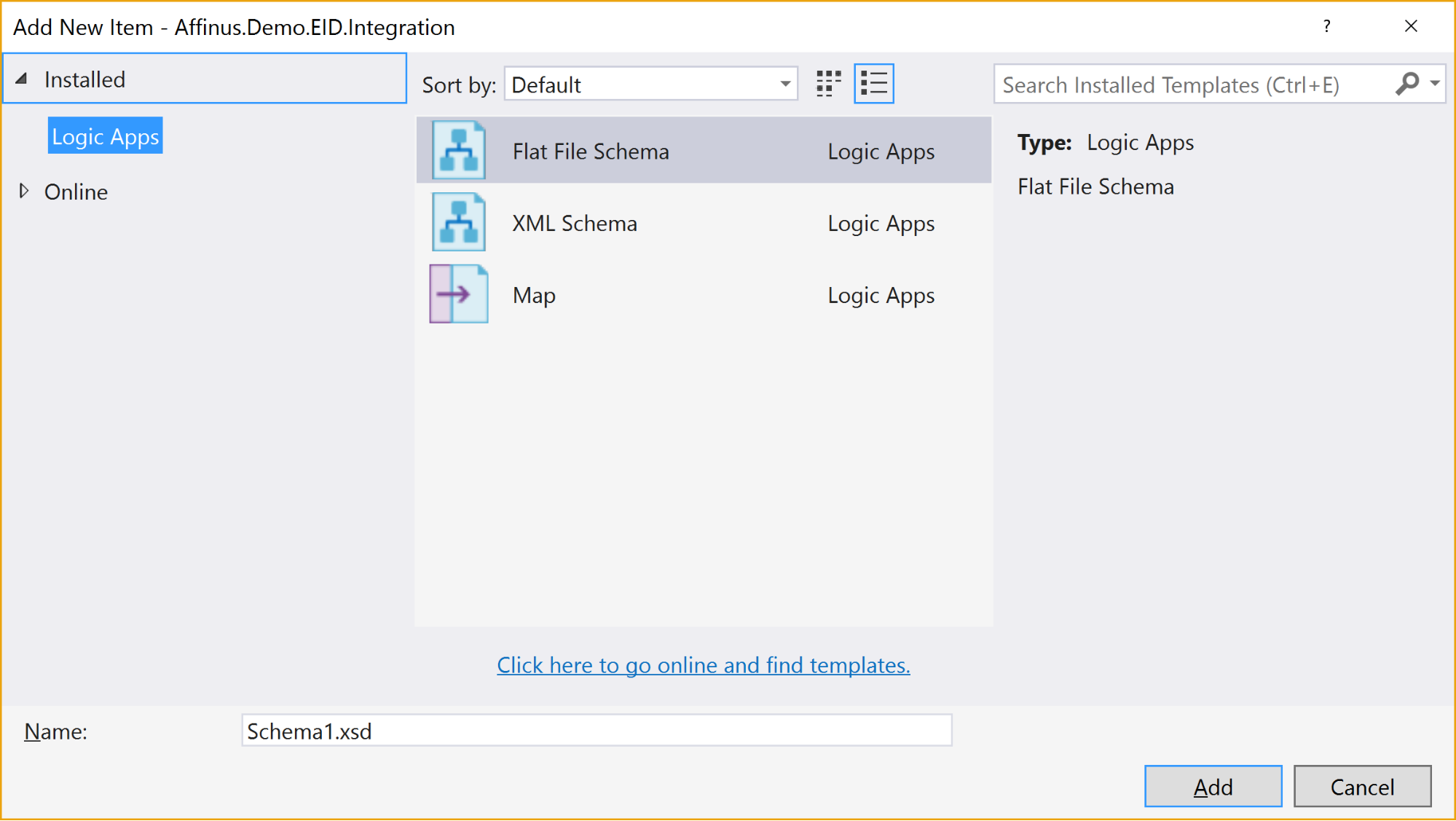
The available items are:
|
Item Name
|
Description
|
|
Flat File Schema
|
Opens the BizTalk Flat File Parser wizard, allowing you to build a flat-file schema (for use with the Flat File Parsing connectors in Logic Apps) from a sample flat file (e.g. csv or positional file).
|
|
XML Schema
|
Opens the BizTalk Schema Editor, which allows you to create/edit an XSD file.
|
|
Map
|
Opens the BizTalk Mapper, which allows you to create or edit a BTM map file.
|
There are a couple of restrictions with this project type:
- You can’t install the Integration Account type on the same PC that has BizTalk Server installed – they use the same components and don’t currently play nice with each other
- Only Visual Studio 2015 is supported (at this time)
- The BTM files generated by the mapper are converted into XSLT files (stored in the bin folder) when the project is built
- You can’t put maps in folders: they need to stay in the root folder
- There is no option to create an Integration Account nor publish the schemas/maps to an existing Integration Account from this project
|
Note: The link to download the Integration Account project extension can be found at the end of this article.
|
|
Note: We recommend that you create a separate Azure Resource Group project that will create the Integration Account in Azure and deploy the schemas/maps from this project. The script for this will be covered in the next article/video.
|
3. Further Reading
How to author an ARM template:
https://docs.microsoft.com/en-us/azure/azure-resource-manager/resource-group-authoring-templates
ARM Template expression and functions:
https://docs.microsoft.com/en-us/azure/azure-resource-manager/resource-group-template-functions
Integration Account visual studio extension
https://aka.ms/vsmapsandschemas
Logic Apps Visual Studio extension
https://visualstudiogallery.msdn.microsoft.com/e25ad307-46cf-412e-8ba5-5b555d53d2d9
by Daniel probert | Mar 8, 2017 | BizTalk Community Blogs via Syndication
Azure Enterprise Integration Series
Part 2: Azure Resource Manager Overview
1. Azure Resource Manager
The Azure Resource Manager (ARM for short) is the deployment engine behind Azure. It’s actually a whole lot more than that, but let’s just start with that.
In a nutshell, we can supply it a description of what we want to create (in a JSON file known as an ARM Template) and it will go away and provision all the required resources. It does this asynchronously, and we can check back regularly to see how it’s getting on.
The beauty of ARM is that we can group our resources however we want, and we can keep the definition of those resources in a single file, or group them in multiple files, depending on our needs.
Each resource to be created is represented by a Provider which uniquely identifies the type of resource being created. For each provider, there is also an API Version, which specifies which version of the resource to create. For example, to create a Logic App, you use a provider type of “Microsoft.Logic/workflows” and an API Version of “2016-06-01” (as at the current date).
Almost every resource in Azure can be created by the ARM engine, and the goal is to support all resource types. For example, you may want ARM to create: a virtual machine, the hard disks, a Virtual Network, Traffic Manager, and then kick off a script that install some software on the VM.
Alternatively, you may use ARM to create some Logic Apps, and API App, an Azure SQL Database, and an instance of API Management.
The ARM engine also sits behind the Azure Portal: when you provision a new resource in the portal (e.g. API Management) the portal sends a REST request to the ARM engine instructing it in what to create.
2. Resource Groups
A Resource Group is a mechanism for grouping a set of related resources in Azure. Any actions you perform on that Resource Group then apply to all the contained resources. The Resource Group also acts as a billing container, allowing you to see the costs of all contained resources.
The main criteria for which resources to group together is that all the resources share the same deployment lifecycle. Ultimately how you group your resources is left up to you, but the general rules to follow are:
- Resources that are exclusively used by an application, should be in the same Resource Group.
- Resources that are shared with other applications should be grouped with other resources used by those same applications
- If you would end up with a whole lot of resources on their own in a Resource Group, look at grouping those in a common Resource Group
- Use Resource Groups to delineate application environments e.g. Dev, Test, UAT, Prod
- For larger applications, it may make sense to split the application amongst multiple Resource Groups e.g. put Web Front end in one Resource Group, and middleware/database in another.
For example, say you had the following application, called CustomerService:
- 3x Logic Apps
- 1x API Apps
- 1x Function App
- 1x Azure SQL Server
If all those resources are only used by the same application, then we put them all in the same Resource Group (called CustomerServiceRG). That way, if we need to tear down the CustomerServiceRG Resource Group (e.g. to move it, or during redeploy) we don’t affect any other application. We can also apply Security (RBAC) and Tagging at the Resource Group level, and have it affect all the resources in the group.
Now imagine that 6 months later, the Azure SQL Server starts being used by 2 other applications.
If we *don’t* move the Azure SQL Server to a separate Resource Group, then next time we tear down the CustomerServiceRG resource Group, we inadvertently break those other two applications.
|
Note: you’ll notice that when you create a resource group, you need to specify a location (i.e. an Azure Data Center). And that you also need to do this when adding resources to the Resource Group.
The location for the Resource group is just the location where Resource Group metadata is stored. It has no bearing on the location where the actual resources are deployed.
In fact, you could have a Resource Group located in North Europe that contained some resources in Wes US, and some in South East Asia.
But for simplicities sake, it’s usually best to keep the Resource Group location, and the resource locations, the same.
One exception might be for Disaster Recovery situations, where you have a supplicate set of resources in a separate region.
|
3. ARM Templates
An ARM Template is a JSON file the specifies the resource that the ARM engine should create.
ARM templates also contains sections to handle parameters that are passed in, variables used during the execution, and for returning outputs.
There is a whole ARM Template language, containing expressions and functions, that you can use (along with the JSON you write) to set values and define the resources. You can read more about the format of an ARM template here, and see a list of supported expression and functions here.
Almost everything in Azure can be represented via an ARM template: Logic Apps are defined in ARM Templates, as are Integration Accounts, App Services, Virtual Machines, Storage Accounts, Service Bus Namespaces/Topics/Subscriptions, etc.
An empty ARM template looks like this:
|
{
“$schema”: “https://schema.management.azure.com/schemas/2015-01-01/deploymentTemplate.json#”,
“contentVersion”: “1.0.0.0”,
“parameters”: {},
“variables”: {},
“resources”: [],
“outputs”: {}
}
|
Looking at the sections above:
3.1 Parameters
The parameters section contains a list of parameter objects, defining the values to be passed into the ARM template (either by an ARM template parameter file, or via a parameter override).
A parameter definition contains:
- The name of the parameter (required)
- The type of parameter (required)
- Minimum length (for string parameters)
- Maximum length (for string parameters)
- Minimum value (for numerical types)
- Maximum value (for numerical types)
- Metadata (e.g. description)
- Default value (if no value passed in) – if this value is missing, it’s a required parameter
- Allowed values (an array of allowed values)
For example, a parameter that passed in a Logic App name might look like this:
|
“logicAppName”: {
“type”: “string”,
“minLength”: 1,
“maxLength”: 80,
“metadata”: {
“description”: “Name of the Logic App.”
}
|
|
Note: Parameterization is a crucial part of integration development in Azure.
|
3.2 Variables
The variables section contains values that are created at the time of deployment, usually from a combination of parameter values and expression/function value.
Variables allow you to simplify your template by putting common values in one place, improving readability and preventing repetition of values.
For example, imagine you have an Integration Account in a Logic App ARM Template.
You reference that Integration Account using an ID, which is a bit like a URL to the Azure resource (in fact, it’s a lot like a relative URL to the Azure resource!).
Suppose you had an Integration Account ID that looked like this:
/subscriptions/aaaaabbbbbbcccccccddddddeeeeeeffff/resourcegroups/integrationaccountresourcegroup/
providers/Microsoft.Logic/integrationAccounts/integrationaccountname
If you needed to reference that Integration Account at multiple places in your Logic App, you’d have the same value repeated in multiple places.
If you wanted to change the Integration Account ID, you’d have to change it at each location in the Logic App.
What would be easier, would be to define the Integration Account ID as a variable:
“variables”: {
“LogicAppIntegrationAccountId”: “/subscriptions/aaaaabbbbbbcccccccddddddeeeeeeffff/resourcegroups/
integrationaccountresourcegroup/providers/Microsoft.Logic/integrationAccounts/integrationaccountname
“
}
And you can then refer to this variable in your ARM Template like this:
variables(‘LogicAppIntegrationAccountId’)
Going one step further, you could parameterize the variable, so that the value came partly from expressions, and partly from passed in parameter values:
|
“variables”: {
“LogicAppIntegrationAccountId”: “[concat(subscription().id,’/resourcegroups/’,parameters(‘integrationAccountResourceGroupName’),
‘/providers/Microsoft.Logic/integrationAccounts/’,parameters(‘integrationAccountName’))]”
},
|
In the example, above, we are assuming that the Integration Account is in the same subscription as the ARM template we’re going to be deploying, and we pass in the name of the Integration Account and the Resource Group it is in.
3.3 Resources
The resources section contains an array of resource objects defining the Azure resources we want the ARM engine to create.
Each Resource object follows a standard format:
|
{
“name”: “”,
“type”: “”,
“location”: “”,
“tags”: {},
“apiVersion”: “2016-06-01”,
“properties”: {},
“dependsOn”: []
}
|
The values above are:
|
Section Name
|
Description
|
|
Name
|
Name of the resource being created
|
|
Type
|
Name of the provider to use for this type of resource e.g. Microsoft.Logic/workflows
Note: provider names are grouped under namespaces. In the example, above, “Microsoft.Logic” is the namespace. Not all providers are supported in all regions.
|
|
Location
|
The region the resource should be deployed in. Note: this doesn’t have to be the same region as the Resource Group.
|
|
Tags
|
Contains metadata for the resource e.g. for a logic app, the displayName value is stored here.
|
|
API Version
|
The specific version of the resource you want to create. API Version change occasionally, usually when a major new release (or breaking change) is introduced. This value allows you to specify which version of the resource you want created, which allows you to maintain compatibility even after a new version is realised.
|
|
Properties
|
The properties for the resource. This is where the actual resource content is stored. For example, for a logic app, this is where the Logic App definition is stored: if you switch to Code View in the Logic App designer, what you’re seeing is this properties value (i.e. you don’ see the rest of the ARM template that defines the Logic App).
|
|
Depends On
|
An array of resource name or IDs that this resource depends on. The ARM engine will build dependent resources first, and in sequence. Any resources that have no dependency are provisioned in parallel. The resources in this array must be defined in this template.
|
|
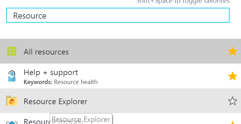
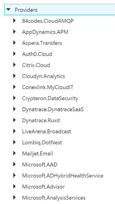
Note: You can see a full list of providers (grouped by namespace) in the portal, by selecting Resource Explorer, and then choosing providers:
|
3.4 Outputs
The outputs section is a list of output objects, which are used to return values after the deployment is complete.
Often, the outputs section is used to return a URL to a resource, or a connection string (e.g. for a Service Bus Namespace).
A output object definition contains:
- The name of the output (required)
- The type of output (required)
- The value being returned
For example, an output that returns the Connection String for a newly created Service Bus Namespace might look like this:
|
“NamespaceConnectionString”: {
“type”: “string”,
“value”: “[listkeys(variables(‘authRuleResourceId’), variables(‘sbVersion’)).primaryConnectionString]”
}
|
4. ARM Template Parameter Files
An ARM Template Parameter File provides an easy way to group all the parameters required for an ARM template into one place.
The Parameter file is a JSON file that contains at least one parameter definition for each required parameter in the corresponding ARM Template.
There is no actual relationship between a parameter file and an ARM template: you could use one parameter file for multiple ARM Template, if the parameter names were the same.
A parameter file looks like this:
|
{
“$schema”: “https://schema.management.azure.com/schemas/2015-01-01/deploymentParameters.json#”,
“contentVersion”: “1.0.0.0”,
“parameters”: {
“logicAppName”: {
“value”: null
}
}
}
|
You can have multiple parameter files for a single ARM Template, with each parameter files containing the values for a given environment (e.g. Dev, Test, UAT, Production).
5. Deploying ARM Templates
There are multiple ways to deploy an ARM template: via the Portal, via the Resource Explorer web site (https://resources.azure.com/), via PowerShell, and directly via the ARM REST API.
To deploy an ARM Template using PowerShell, you use the New-AzureRmResourceGroupDpeloyment cmdlet:
|
New-AzureRmResourceGroupDeployment -Name DeploymentName `
-ResourceGroupName ResourceGroupName `
-TemplateFile ARMTemplateFile `
-TemplateParameterFile ParameterFile `
|
When you execute this cmdlet, you’ll get back a Tracking ID you can use to check the deployment status: this is because the deployment is asynchronous.
An ARM Template can only be deployed to a single Resource Group – you can’t have an ARM Template that spans Resource Groups.
However, you *can* have multiple ARM templates that all deploy to the same Resource Group: this allows you to separate resources into separate ARM templates by resource type, for example. You could then have all your Logic Apps in one ARM template, Storage Accounts in another, etc.
ARM Templates can be deployed in one of two modes:
- Full: In full mode, all existing resources in the Resource Group are removed, and only the resources in the ARM Template are deployed.
- Incremental: In Incremental mode, the ARM engine compares the resources in the ARM Template to the existing resources in the Resource group, and only deploys what has changed e.g. it might add some resources, and modify others, but it won’t remove any.
Incremental mode is what allows us to separate resources into multiple ARM Templates.
6. Obtaining ARM Template Samples
ARM templates can be obtained in several ways:
- Via the Resource Explorer application (https://resources.azure.com/)
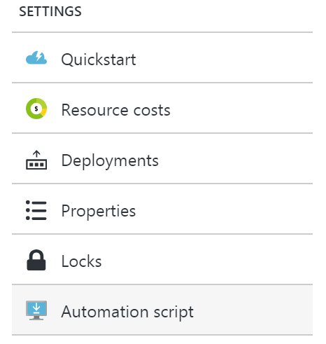
- From the Portal, using the Automation Script option:
- Via PowerShell cmdlets
- From the ARM management REST API
As an integration developer, it’s important that you learn how to author ARM templates: not all resources (in fact very few) have a visual designer. Instead, you either need to create your resources in the Portal and export the ARM Template; or you need to manually create the ARM Template in Visual Studio.
The best option is to have a library of ARM templates which you can then modify to suit your needs.
7. Further Reading
How to author an ARM template:
https://docs.microsoft.com/en-us/azure/azure-resource-manager/resource-group-authoring-templates
ARM Template expression and functions:
https://docs.microsoft.com/en-us/azure/azure-resource-manager/resource-group-template-functions
by Steef-Jan Wiggers | Feb 23, 2017 | BizTalk Community Blogs via Syndication
Microsoft has made the Logic Apps General Available (GA) a few months ago (end of July 2016) and this Azure service has evolved ever since. Each month the product group responsible for the service, Jeff Hollan and Kevin Lam together with Jon Fancey, present updates through a YouTube channel. The latest update (26 January 2017) included for instance, browsing enhancements for connectors, switch case condition (similar to C# switch), JSON Parse to tokenize properties, new SaaS connectors, operations and upcoming new features.
Besides the evolution and thus an increase in maturity, the adoption of Logic Apps rises. I myself and a colleague at Macaw have built and deployed a Logic App solution for a customer in production that runs for over a month now without any issues. And we are not the only ones as there are many more customer cases. Businesses start seeing the added value brought by Logic Apps with its connectors, short lead times and no requirements for servers. Logic Apps run in Azure and are Server less, i.e. you can have an enterprise ready integration solution running in the cloud for low cost and maintenance (TCO).
This blog post will provide some additional insight on the power and value of Logic Apps. It can be seen as a game changer concerning integration in the cloud. Logic Apps fall under the moniker integration Platform as a Service (iPaaS), which is what actually is, and I will be quoting Wikipedia here to emphasize this:
“The most common cloud-based integration service model is iPaaS (Integration Platform as a Service), which is a suite of cloud services enabling customers to develop, execute and govern integration flows between disparate applications. Under the cloud-based iPaaS integration model, customers drive the development and deployment of integrations without installing or managing any hardware or middleware.”
You provision a service/host, define the logic and execute in Azure. And iPaaS service is characterized as (according to Wikipedia):
| Characteristic |
Azure |
| Deployed on a multi-tenant, elastic cloud infrastructure. |
The Logic App service |
| Subscription model pricing (OPEX, not CAPEX) |
Consumption Plan |
| No software development (required connectors should already be available) |
Logic App Definition, the available connectors (i.e. managed and/or custom) and actions |
| Users do not perform deployment or manage the platform itself |
ARM Template and the Azure Portal for management |
| Presence of integration management & monitoring features |
Logic App overview (blades), integration with OMS |
Scenario
In this blog post I would like to share another use case or scenario of a Logic App to demonstrate its value and some of the new features. We will build a scenario to demonstrate API integration, where the focus is on connecting different API’s. One common reason for doing this is to automate more of a business process. And Logic Apps can facilitate the integration of one or multiple API’s.
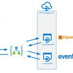
A Logic App will be a composite service that, based on a set of parameters, will provide a result containing weather and event details. The parameters will be city for which you like to know the details about the weather the coming 7 days and events in that time frame. The Logic App will call two API’s hosted in API Management, and combine the result of each call into one single response to the client. The complexity of calling the API’s is abstracted away in API Management, and the composition of the response of both API’s is done in the Logic App.
Building the API
The API’s are generally available API’s, which will be abstracted away from the Logic App by creating a proxy in API Management. In API Management, we will create an API to add operations to them and tie them to the actual API and its operations combined with policies to manage security, and other quality aspects. We provide a name for the API, set the Web service URL (endpoint of the API) and can observe the actual WebAPI URL i.e. API Management instance name with a standard DNS addition .azure-api.net + suffix.
The WebAPI will have an operation daily that connects to the daily forecast operation of the WeatherAPI (api.openweathermap.org) and its parameters.
A policy will be applied to the operation, to add an APPID key in the query parameters.
<policies>
        <inbound>
                <set-query-parameter name="APPID" exists-action="append">
                        <value>67b0fe39a73fdf8c5045f9538270cee4</value>
                        <!-- for multiple parameters with the same name add additional value elements -->
                </set-query-parameter>
                <rewrite-uri template="daily" />
        </inbound>
        <backend>
                <forward-request />
        </backend>
        <outbound />
        <on-error />
</policies>
The policy ensures that the operation can be executed, as the APPID is mandatory in the query parameters. However, the consumer of the Azure API is unaware of this as it is abstracted away through the policy. The same process will be done in the event API (api.eventful.com).
Build the function
A HTTP function will merge the two bodies i.e. JSON strings into one and currently there is no action for it. Hence, we will build a function that will accept a string with two JSON bodies in them.
In general, when it comes to certain operations on your data within a Logic App, you will notice that a function can help facilitate in having that specific capability like merging JSON strings or perhaps date time manipulation. In our scenario, we’ll merge the two JSON responses to one using a function that can be called through HTTP. It is one big string that will be sent to a function, and with a Web Hook type of function it expects a JSON! A HTTP Function can accept a string, manipulate it and return a JSON as shown below.
The two JSON response bodies are concatenated together when calling the function, which means the braces }{ need to be replaced by a comma ‘,’ to form a JSON again.
Building the Logic App Definition
The Logic App itself is a service, i.e. the infrastructure is in Azure and once provisioned you can define your logic. Logic in this context is a definition with a trigger and one or more actions. To define the trigger and action we will have a designer available to add the trigger followed by actions and/or workflow specific actions i.e. for instance a condition, case or scope.
The switch case is one of the new additions.
The Logic App definition of our solution will have a HTTP request trigger followed by an action to consume the weather API and later the event API. It contains a switch to support the possible responses from the API i.e. HTTP status like 200, 400 or other. And based on those types of responses you have a switch in place to control the various outcomes of your Logic App. A 200 will mean proceed to call the next API or create some sort of response to the caller of your Logic App. In status 200 branch, a JSON parse will be used to tokenize the JSON response from the weather API. The JSON parse is another recently added action in Logic Apps as discussed in the introduction. Subsequently, the event API operation search will be called and if the HTTP status is 200, the left branch will call the function through HTTP presenting both response (bodies) to create a JSON response, which will be returned to the client as a response. If the call to search fails, the right branch will return a custom response.
Test the Logic App
To test the Logic App, we will use Postman to send a request (POST) with a payload. This payload will contain a city, start- and end date.
In the Azure Portal we can observe the detail of the Logic App run and drill down into each of the actions. And this is a great feature of Logic Apps, you can see what happens and even resubmit, which is very useful to investigate where failures happen or change the flow in the designer and then resubmit. You do have to use a client like Postman to resubmit!
The Logic App provides monitoring capabilities in its blade like metrics. You can monitor your runs and select metrics to see how your Logic App definition i.e. flow performs.
Metrics are not the only feature within the monitoring section of Logic App. You have diagnostics, and logs you can examine. Thus, its adheres to the characteristic of “Presence of integration management & monitoring features” of iPaaS.
Considerations
Logic App can add value to the business with automating processes, which are agile by the nature of this Azure Service. A process can be created and operational in hours instead of days, can be changed on the fly or replaced by a new process i.e. Logic App. Logic Apps will bring IT closer to the business than ever before. The tremendous number of connectors lowers the connectivity barrier or API’s can be tied together as shown in this blog post as a composite service or to create a business flow/process (orchestration).
However, the power and agility of Logic Apps will also bring the risk of losing grip on the processes if everyone can easily build these flows and run them, i.e. you will need some form of governance to prevent the business completely go wild with this service. With a great deal of flexibility or agility and lower barrier to build integrations some form of governance will necessary to prevent overlap, over consumption, and conflicts.
Logic App can be viewed as a counterpart for BizTalk Server, a server product from Microsoft suitable for application integration. In BizTalk business processes can be automated by connecting two or more applications or services. In this blog post we have seen that two API calls are combined to create one response. However, Logic Apps with its various connectors can do the same thing as we did with BizTalk on premise. With BizTalk, we can create a composite application similar to what we have shown in this post by providing a common front end to a group of existing applications. Hence the value BizTalk provided on premise is now available through Logic Apps. The most important difference is hosting and pricing i.e. cloud versus on premise and license fees versus pay as you go.
Logic Apps can be called directly through HTTP and thus are exposed to world wide web i.e. everyone, which means it will need some sort of security. Out of the box is that a signature (SAS) is bound to the endpoint and is required for clients to provide in the request. Some see this as a form of security by obscurity and to further enhance security you can use API Management. API Management abstracts away the security and you can enforce other means of security to access the endpoint i.e. OpenID or OAuth 2.0.
Supporting the solution such as the one described in this post can be a challenge since you need to monitor or keep an eye out for the API keys at API supplier i.e. the weather API and event API, key(s) for the function and SAS signature in the Logic App endpoint, and the consumption of the Logic App. Each action in Logic App is an Azure consumption and has a price, which can be monitored easily through observing the resource costs in a resource group; it is operational costs of executing Logic Apps. You have to factor in notifications and alerting in your solution, which is easy to set up using alert rules on your resource.
Call to Action
You can learn to work the service yourself, learn more about or express your wishes:
Author: Steef-Jan Wiggers
Steef-Jan Wiggers has over 15 years’ experience as a technical lead developer, application architect and consultant, specializing in custom applications, enterprise application integration (BizTalk), Web services and Windows Azure. Steef-Jan is very active in the BizTalk community as a blogger, Wiki author/editor, forum moderator, writer and public speaker in the Netherlands and Europe. For these efforts, Microsoft has recognized him a Microsoft MVP for the past 5 years. View all posts by Steef-Jan Wiggers

by Rene Brauwers | Dec 20, 2016 | BizTalk Community Blogs via Syndication
In our previous post, I guided you through setting up a WCF service and protecting it using URL Authentication. Although a lengthy post you would have noticed that setting up url-authentication is actually quite simple and only involving a few steps.
Anyways, in this post we will be focusing on adding the integration magic, without adding a single line of custom code, using Azure Logic Apps.
The integration magic which we will be adding will take care of the following functionality within our end-to-end scenario.
A request will come in which will start our process which is to retrieve a list of customers.
The customer information to be retrieved combines the result from two sources; the first source being the WCF service we build in our previous post and the second source a public rest api. The data which is to be returned to the caller as such will consist of the base data originating from the wcf services enriched with data obtained from the public rest api.
Visualizing the flow
Before we start implementing the solution using Logic Apps it is always a good practice to work-out the actual process flow using a tool such as Microsoft Visio.
Having said that, let’s eat my own dogfood. Low and behold, see below the diagram depicting the process and an explanation of the process.
The process kicks off whenever a http post requesting a list of customer data is being made to Logic Apps (1). Once received within logic apps a new message (soap request) has to be created (2). Once created this message is being offloaded to the custom WCF service (3), we created in the previous post. If the call is successful the webservice will return a list of customers (4). The information contained within the response contains the following data: customerId, FirstName, SurName and postcode.
The postcode value(s) contained within this response is subsequently used to retrieve detailed location information.
In order to retrieve this location information, logic apps will perform a loop over the response message (5), extract the postal code and invoke a custom rest API to do the location lookup (6). The response received contains the following data: Suburb name, postcode, state-name, state abbreviation, locality and the latitude and longitude of the locality.
This data and the basic customer data is then combined and temporarily persisted in DocumentDB (7).
//Reason, for leveraging this external persistence store is to make life easier for us, as we want //enrich all the customer data with additional information retrieved from the second api call and //return it in one go to the caller. Currently there is no easy way of doing this directly from within //logic-apps as, however, have no fear; in one of the next releases a feature to store session state //within a logic app will be implemented and thus we would no longer need to result to an //intermediate ‘session state’ store.
This process is then repeated for all customers and once we have iterated over all customer records we exit the loop and retrieve all ‘enriched’ documents stored in DocumentDB (8) which we then will return to the caller. The information returned to the caller will then contain the following data; FirstName, LastName and Location information consisting of Locality, State Name, SubUrb, Postcode and longitude and latitude (9).
Provision the logic App
At this point we have worked out the high-level flow and logic and as such we can now go-ahead and create the logic app, so let’s go ahead and do so
1. Login to the Azure Portal
2. Select the resource-group which you created in part-1, in which you deployed your custom wcf service. In my case this resource-group is called Demos
3. Once the resource-group blade is visible, click on the Add button
4. A new blade will popup, within this blade search for Logic App and click on the Logic App artefact published by Microsoft and of the Category Web + Mobile
5. Click on create
6. Now fill out the details and once done click Create, after which your logic app will be created
7. Once the logic app has been created, open it and you should be presented with a screen which allows you to create a new logic app using one of the pre-build templates. In our case we will choose the “Blank LogicApp”
Implement the ‘Blank LogicApp’
Once you’ve clicked on the blank logic app template, the designer will pop up. We will be using this designer to develop the below depicted flow which will be explained in the following sections. Well let’s get started.
Step 1: Request Trigger
Within this designer, you will be presented with a ‘card selector’. This card selector, being the first of many, contains so-called triggers. These triggers can best be explained as ‘event listeners’ which indicate when a logic app is to be instantiated.
In our scenario, we want to trigger our logic app by means of sending a request. So, in our case we would select the Request trigger. Now select this Request Trigger.
To dig up more information regarding the different triggers and actions you can click on the Help button, which will open up a Quick Start Guide blade containing links too more information.
Configure
Once you’ve selected the trigger, the Request Trigger ‘Card’ will be expanded and will allow you to configure this trigger.
1. This section is not customizable, but once the logic app is saved will contain the generated endpoint. This endpoint is to be used by clients who which to invoke the logic app.
2. The request body JSON schema section, is an optional section, which allows us to add a schema describing what the inbound request message should look like.
You might be wondering why bother? Well if we bother by adding a schema we get the benefit of an ‘intellisense like’ experience from within the designer, which can help us down the road in case we want to easily access one of the properties of the request message in a follow up action.
So let’s go ahead and add a schema. In our case, we will only require one property to be send to our logic-app and this property is RequestId. We will be using the property further down the stream to uniquely identify the request and use it to store our ‘session state’.
As such our Json request can be represented as follows:
{
“RequestId”:”2245775543466″
}
Now that we know what the payload message looks like, we need to derive the Json schema. Well luckily for us, we can go to JSONSchema.net and generate a schema. J The generated schema, subsequently would be represented as
{
“type”: “object”,
“properties”: {
“RequestIds”: {
“type”: “string”
}
},
“required”: [
“RequestIds”
]
}
At this point we have all the information required to fill out the ‘Request Body JSON Schema’ section, so all we have to do is copy and paste it into that section.
3. At this point we are ready to proceed with our next step. Which according to our high-level design consists of an activity which composes a new message, which represents the request message (soap) which is to be send to the customer WCF service.
So, let’s proceed and click on the + New Step button
4. Now several options appear, but we are currently only interested in the option ‘Add an action’, so select this.
Step 2: Compose SOAP request message
As part of our last step we clicked on the “new step” button and selected “Add an action”. Which subsequently would display the ‘card selector’ again, only this time displaying available actions to choose from.
Please note: typical actions to choose from would include
· connectors to SaaS services such as Dynamics CRM Online, on premise hosted Line of business applications such as SAP and connectors to existing logic-apps, azure functions and API’s hosted in API Management
· typical workflow actions which allow us to delay processing or even allow us to terminate further processing.
Looking back at our overall scenario which we are about to implement one of the initial actions would be retrieving a list of customers.
In order to retrieve this list of customers we would need to invoke our Customer WCF service, we build earlier. As our WCF service is SOAP based, it requires us to implement one additional step before we can actually invoke the service from within Logic Apps and this steps involves creating the SOAP request message, using a Compose Action.
So from within the ‘Card Selector’ select the compose Action.
Please note: In the near future this additional step will no longer be required as API Management will be able to RESTify your soap endpoints which than can easily consumed from within logicapps (see roadmap). Besides having functionality in API Management, the chances are pretty good as well that a first-class SOAP connector will be added to logic apps in the future as it is ranked high on the logic apps functionality wishlist.
Configure
Once you’ve selected the compose action the following ‘Card’ will show up on in the designer which allows you to compose a Message, which in our case will be the SOAP Request message.
1. The input section allows us to construct the soap (xml) message, which will act as the request which we will be sending to our customer WCF service.
So how would you determine what this message would look like. Well the easiest way would be by using a tool such as SOAPUI which can generate a sample request message. In the previous post, I’ve added a section which explains how to do this and in our scenario the soap request message looks as follow:
<?xml version=”1.0″ encoding=”UTF-8″?>
<Envelope xmlns=”http://schemas.xmlsoap.org/soap/envelope/”>
<Body>
<GetCustomers xmlns=”http://tempuri.org/” xmlns:xsi=”http://www.w3.org/2001/XMLSchema-instance” />
</Body>
</Envelope>
2. Once we have our sample SOAP request message, we simply copy and paste it into the input field.
Please note; once you click on the Inputs section a windows will appear which will allow you to select ‘dynamic content, used within this flow’. This is the ‘intellisense like’ experience I referred to earlier in this post. Anyways we will be ignoring this for now, but in future steps we will be using this.
3. At this point we are ready to proceed with our next step. Which will actually call our customer WCF service.
So, let’s proceed and click on the + New Step button
4. Once again several options appear and once again select the option ‘Add an action’.
Step 3: Invoke our Customer WCF Service
After completing step 2 we are now able to actually implement calling our customer WCF service. In order to do so all, we need to do is select the ‘HTTP’ Action from within the ‘Card Selector’
Configure
Once you’ve selected the HTTP action the following ‘Card’ will show up on in the designer which allows you to configure the HTTP request in order to receive the customer information.
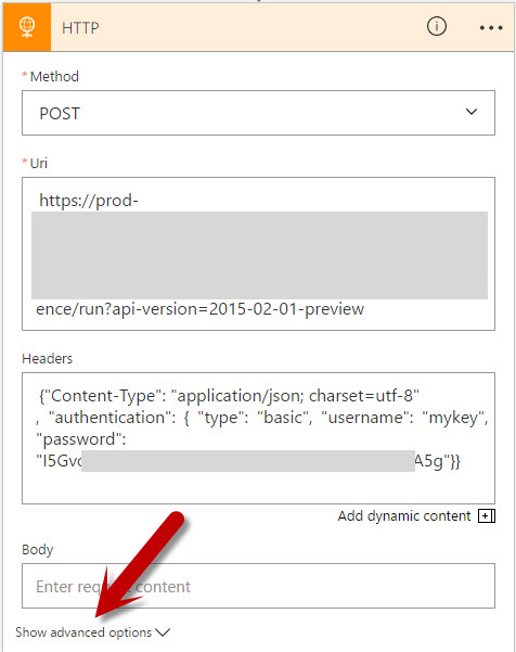
As you might remember the custom WCF Service which we are about to invoke uses URL Authorization using Azure Active Directory (see previous post) and as such requires any (POST) request to be authenticated. Long story short; One of the nice things of the HTTP action is that it makes it a breeze invoking web-services even if they require authentication, all we need to do is configure the action correctly and this is done by expanding the advanced options of the HTTP Card, which will allow us to do so.
1. The Method which we need to select is ‘POST’ as we will be posting the soap request to the customer WCF service.
2. The Uri sections allows us to enter the Request URL of the web-service. In our case that would be https://demo-apis.azurewebsites.net/Customers.svc
3. The Headers sections will be used to add both the SOAP Action which needs to be invoked as well as the Content-Type of the actual request message.
The easiest way to retrieve the SOAP Action would be by means of SOAPUI as well. So from within SOAPUI open the request and then select WS-A (bottom menu-bar), and then copy and paste the Action
The header information needs to be passed in as a Json string, and looks as follows
{
“Content-Type”:”text/xml”,
“SOAPAction”:”http://tempuri.org/ICustomers/GetCustomers”
}
4. The body section will contain the message which we composed in the previous step. As such once you click in this section, additional information will displayed on the desiger which allows you to select ‘dynamic content’. (this is the ‘intellisense like’ experience I referred to earlier). From this menu, select the variable ‘’ This variable contains the message which we composed earlier.
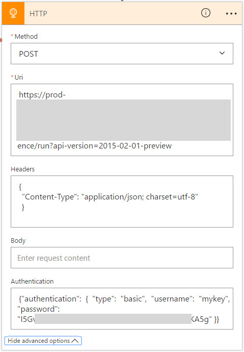
5. Now click on the Show Advanced Options, which will allow us to fill out the required authentication information.
6. From the dropdown select Active Directory OAuth
7. For Active Directory OAuth we will require to fill out the Tenant, Audience, Client ID and Secret. This information is to be retrieved as follows
a. In the Azure Portal, go to Azure Active Directory Blade and click on APP Registrations
b. Select the application in question (see previous blog-post) which you registered for the WCF Customer service. In my case demo-apis
c. Now on the settings blade click on Properties and make a note of the following:
Application ID – This is the equivalent of the Client ID
App ID Uri – This is the equivalent of the Audience
d. GO back to the settings blade, click on Keys
e. Now it is time to generate the secret. In order to do this, add a description and select how long the secret should be valid. Once done save the entry and make a note of the value (this is the secret)
f. Now on the portal page, click on the Help Icon and select ‘Show diagnostics’
g. In the window, which pops up, search for tenants. Find your tenant (most likely the one which states ‘isSignedInTenant = true’ and note down the Tenant ID
h. At this point we have all the information in order to fill out the required information
Test
Now that we’ve implemented the call, it would be a good time to go ahead and test the logic app. Luckily for us, this is quite simple.
1. Click on the Save button to save your logic app
2. Now Click on the run button.
3. Wait a few seconds and you should see a debug output. If everything went Ok, it should look similar to the image below.
4. Now click on the HTTP – GetCustomers shape. Which allows you to look at the debug / tracking information. It will show you the input as well as the output information.
5. Now go to the OUTPUTS section and copy and paste the Body section. We will be needing this in Step 4 J
Step 4: Loop over the customer result
Our last step resulted in the fact that we configured our HTTP Action which was responsible for invoking our customer wcf service and returning us a list of customers.
Now in this step we will need to loop over the returned customer list, such that we can enrich each individual record with localization information obtained from a different API.
In order to do so we will have to select a for-each action. This action can be selected by clicking on the “+ New Step button”. Several options will appear of which we need to select the ‘more’ followed with the ‘add a for each’ action.
Configure
1. Once the for-each step has been selected it is being dropped on the designer. The designer than offers us a section in which we can add in input over which we want to loop.
2. If our WCF service would have returned an Json Array object, we would have been able to simply select this output using the ‘Dynamic Content’ selection process (aka intellisense). However in our case the output over which we want to loop is a customer resultset formatted in XML. So, in our case we will need to help the the logic-apps engine a bit, and they way to do this, is by adding a custom expression. Which in our case is a Xpath expression, pointing to the node over which we want to loop.
The xpath expression in our case would be:
/*[local-name()=”Envelope”]/*[local-name()=”Body”]/*[local-name()=”GetCustomersResponse”]/*[local-name()=”GetCustomersResult”]/*
Easiest way to test this xpath expression, would be by using the response message we extracted when we tested our logic app earlier and subsequently use an online tool to test the xpath expression.
Now that we have our xpath expression, we can use it in the following Logic App Expression
@xpath(xml(body(‘Replace with the name of action of which we want to use the response’,’Xpath Expression’)
In my scenario the expression would be as follows
@xpath(xml(body(‘HTTP_-_GetCustomers’)), ‘/*[local-name()=”Envelope”]/*[local-name()=”Body”]/*[local-name()=”GetCustomersResponse”]/*[local-name()=”GetCustomersResult”]/*’)
Step 5: Extract individual customer info
In our previous step we instantiated our for-each loop which will loop over our xml result set. Now our next step is to extract the individual customer info and store it in a intermediate json format which we will be using in subsequent actions.
So from within our for-each action, select the Add an action.
From within the ‘Card Selector’ select the compose Action.
Configure
Once you’ve selected the compose action the following ‘Card’ will show up on in the designer which allows you to compose a Message, which in our case will be a custom Json message which holds the individual customer information consisting of CustomerId, FirstName, LastName and PostCode
Note: As in Step 4 when configuring the for-each iteration path. We will be leveraging xpath expressions in order to extract the individual customer data. Alternatively, I could have leveraged an Azure Function to convert the received XML Customer response into JSON or I could have leveraged API Management which by means of policies can perform conversion from xml to json out of the box. In my next post (part 3 of this series) I will be using this.
.
1. The input section allows us to construct our custom Json message which holds the individual customer information consisting of CustomerId, FirstName, LastName and PostCode
2. In order to extract the required fields from the xml will be leveraging the following xpath queries
a. customerId extraction:
string(/*[local-name()=”CustomerData”]/*[local-name()=”CustomerId”])’)
b. FirstName extraction:
string(/*[local-name()=”CustomerData”]/*[local-name()=”FirstName ”])’)
c. SurName extraction:
string(/*[local-name()=”CustomerData”]/*[local-name()=”SurName”])’)
d. PostCode extraction:
string(/*[local-name()=”CustomerData”]/*[local-name()=”PostCode”])’)
the logic app expression which we will be leveraging to extract a value using xpath will be
@{xpath(xml(decodeBase64(item().$content)), ‘Xpath Expression‘) where item() refers to the current item (customer record) in the loop and $content represents the content (customer record xml part)
Combined in a Json construct the complete message construction would look like (note that we escape using )
{
“CustomerId”: “@{xpath(xml(decodeBase64(item().$content)), ‘string(/*[local-name()=”CustomerData”]/*[local-name()=”CustomerId”])’)}”,
“FirstName”: “@{xpath(xml(decodeBase64(item().$content)), ‘string(/*[local-name()=”CustomerData”]/*[local-name()=”FirstName”])’)}”,
“LastName”: “@{xpath(xml(decodeBase64(item().$content)), ‘string(/*[local-name()=”CustomerData”]/*[local-name()=”SurName”])’)}”,
“PostCode”: “@{xpath(xml(decodeBase64(item().$content)), ‘string(/*[local-name()=”CustomerData”]/*[local-name()=”PostCode”])’)}”
}
Test
Now that we’ve implemented the xml extraction within the for-each, it would be a good time to go ahead and test the logic app, and see if everything works accordingly.
1. Click on the Save button to save your logic app
2. Now Click on the run button.
3. Wait a few seconds and you should see a debug output. If everything went Ok, it should look similar to the image below.
4. As you can see the last item in the flow, contains a Json output depicting the customer values extracted.
Step 6: Invoke the postcodeapi
Now that we have extracted our customer data and stored it in a json format. We can proceed with the next step, which invokes invoking a public postcode api. In order to do so we will once again select the HTTP Action within the ‘Card Selector’
Configure
Once you’ve selected the HTTP action the following ‘Card’ will show up on in the designer which allows you to configure the HTTP request in order to receive localization information based on a postal code.
1. The Method which we need to select is ‘GET as we will be retrieving data from a rest endpoint.
2. The Uri sections allows us to enter the Request URL of the web-service. In our case that would be http://v0.postcodeapi.com.au/suburbs.json?postcode=XXXXX where XXXX is a dynamic parameter, to be more specific; we will be using the PostCode field which we extracted in step 5. In order to use this PostCode value we will
a. Enter the value http://v0.postcodeapi.com.au/suburbs.json?postcode= in the Uri field.
b. Select the dynamic content ‘Outputs’ from the Extracted xml
We are currently not able to directly access the PostCode field from within the designer as the designer currently is not aware of this property. It is only aware of the fact that the ‘compose step – Extracted xml’ has a output which is a ‘message’ and as such we can only select the complete message.
Note: In a future release of logic-apps this experience will be improved and additional magic will be added such that the designer can ‘auto-discover’ these message properties. How this will be implemented is not 100% clear, but one of the possibilities would be; that we would manually add a ‘description’ of the output (Json schema, for example) to the compose action or any other action which returns / creates an object.
3. In order to select the PostCode field from the Outputs, we will be needing to switch to Code View.
4. Once in code view, find the code block which contains the http://v0.postcodeapi.com.au/suburbs.json?postcode= url. Once found we simple modify the code from
http://v0.postcodeapi.com.au/suburbs.json?postcode=@{outputs(‘Extracted_xml’)}
to
http://v0.postcodeapi.com.au/suburbs.json?postcode=@{outputs(‘Extracted_xml’).PostCode}
5. Now go back to the designer
6. And behold the designer now states “http://v0.postcodeapi.com.au/suburbs.json?postcode={} PostCode”
Test
Now that we’ve implemented the postcode api call, it would be a good time to go ahead and test the logic app.
1. Click on the Save button to save your logic app
2. Now Click on the run button.
3. Wait a few seconds and you should see a debug output. If everything went Ok, it should look similar to the image below. If you expand the HTTP action, you wull notice that the URI now is composed using the extracted PostCode value
Step 7: Compose an enriched customer message
Now that we have invoked the postcode API it is time to combine both the original customer data and the postcode data. In order to do this, we will be composing a new Json message using the Compose Action.
From within the ‘Card Selector’ select the compose Action.
Configure
Once you’ve selected the compose action the following ‘Card’ will show up on in the designer which allows you to compose a Message, which in our case will be a new Json message which holds both the customer data as well as the location data retrieved from the PostCode lookup.
1. The input section allows us to construct our custom Json message which will hold all the combined data
2. Now copy and paste the below ‘sample’ json message into the input section
This message will be of the following structure:
{
“FirstName”: “## FirstName from the WCF Customer web service##”,
“LastName”: “## LastName from the WCF Customer web service##”,
“Location”: {
“Latitude”: “## Latitude obtained from the postal api##”,
“Locality”: “## Locality obtained from the postal api##”,
“Longitude”: “## Longitude obtained from the postal api##”,
“PostCode”: “# PostCode from the ‘extract_xml’ message##”,
“State”: “## State obtained from the postal api##”,
“Suburb”: “## Suburb obtained from the postal api##”
},
“RequestId”: “## Obtained from the request trigger##”,
“id”: “# CustomerId from the ‘extract_xml’ message##”
}
3. Now go to code view
4. Once in code view, find the code block which represents the Json message which we just copied and pasted in the input section.
Note: In a future release of logic-apps this experience will be improved and additional magic will be added such that the designer can ‘auto-discover’ these message properties, which we will now add manually. How this will be implemented is not 100% clear, but one of the possibilities would be; that we would manually add a ‘description’ of the output (Json schema, for example) to the compose action or any other action which returns / creates an object.
5. Now replace the json such that it looks like depicted below
“Enrich_with_postal_code”: {
“inputs”: {
“FirstName”: “@{outputs(‘Extracted_xml’).FirstName}”,
“LastName”: “@{outputs(‘Extracted_xml’).LastName}”,
“Location”: {
“Latitude”: “@{body(‘HTTP’)[0].latitude}”,
“Locality”: “@{body(‘HTTP’)[0].locality}”,
“Longitude”: “@{body(‘HTTP’)[0].longitude}”,
“PostCode”: “@{outputs(‘Extracted_xml’).PostCode}”,
“State”: “@{body(‘HTTP’)[0].state.name}”,
“Suburb”: “@{body(‘HTTP’)[0].name}”
},
“RequestId”: “@{triggerBody()[‘RequestId’]}”,
“id”: “@{outputs(‘Extracted_xml’).CustomerId}”
},
“runAfter”: {
“HTTP”: [
“Succeeded”
]
},
“type”: “Compose”
},
Test
Now that we’ve composed a message containing both the WCF and PostCode API data, it would be another good time to go ahead and test if everything works and this time we will be testing our logic app using Fiddler
1. Download Fiddler, if you already have.
2. Go to you logic app and expand the Request Trigger and press on the “Copy Icon”, this will copy the logic app endpoint to your clipboard.
3. Open fiddler, and select the composer tab
4. In the composer
a. Set the HTTP Action to POST
b. Copy and Paste the uri in the Uri field
c. In the header section add
i. Content-Type:application/json
d. In the body section add the following json
{
“RequestId”:”20161220″
}
e. Click on the Execute button
5. Now go back to your Logic App
6. In the run history, select the last entry
7. If everything went Ok, it should look similar to the image below.
Step 8: Store Session State in DocumentDB
At this point we have implemented functionality which
· allows us to iterate over all the customer records
· retrieve localization data from the postal code api using the postal code extracted from the customer record.
· Compose a new message which contains all the data.
The functionality which is left to implement at this point in time consists of; combining all the composed new messages, containing the customer and localization data, in one document and returning it to the caller.
Note: Currently there is no easy way of doing this directly from within logic-apps as logic apps currently does not contain the functionality which would allow us to ‘combine the data’ in memory. But have no fear; in one of the next releases of Logic Apps will have support for storing session state and once this is available we will no longer require this additional step, which is explained below.
Configure
As Logic Apps currently has no means of storing session state, we will be resorting to an external session state store. In our case, the most obvious choice would be DocumentDB.
So before we proceed, let’s go and create a DocumentDB service.
1. Go to the Azure Portal and click on the New Icon
2. Search for DocumentDB
3. Select DocumentDB from Publisher Microsoft
4. Fill out the required information and once done create the DocumentDB instance
5. After creation has completed, open the DocumentDB Instance.
6. Now Add a Collection
7. Fill out the required information for the Collection Creation, and press OK once done
8. Go back to the main DocumentDB Blade, and click on Keys
9. From within the Keys, Copy and Paste the Primary or Secondary Key
10. Now go back to our logic app, and open it in the designer
11. In the Logic App, Click on the Add New Item
12. Now search for DocumentDB Actions and select “Azure DocumentDB – Create or update document”
13. The connector will now be displayed and will require some configuration
14. Fill out the required information. For which it has to be noted that for Database Account Nam is the actual name of the documentDB. In my case docdb-playground.
15. Once filled out the information should look similar to the one depicted below in the image
16. At this point the connection has been created, and we can now proceed with the actual configuration in which we will
a. select the correct Database ID from the dropdown
b. select the collection to use
c. add the dynamic content (message) which we want to store
d. we set the value to True for IsUpsert
Step 9: Exit Loop, Retrieve and return Stored Data
Our last step resulted in the fact that we persisted all documents into DocumentDB. Now before we proceed, let’s have a look at Step 7 in which we composed the following message, which eventually was stored in DocumentDB.
Have a good look at the field: RequestId. This field is actually passed in whenever we invoke our LogicApp. (see step 7, the test section).
There was a reason why we added this field and have it stored in DocumentDB. The reason? Well this way we are able to select all documents stored in DocumentDB belonging to the specific ID of the current Request and return them to the caller.
Configure
1. Select the Add an action button located just below the for-each scope.
2. Now search for DocumentDB Actions and select “Azure DocumentDB – Query documents”
3. The Document DB Query Documents connector, can now be configured as follows
a. Select the correct database ID from the dropdown in our case ProcessingState
b. Select the applicable collection from the dropdown in our case LogicApp
c. Now add a query, which will return all documents stored in the collection which have the same request id.
SELECT c.Id as CustomerId, c.FirstName,c.LastName,c.Location FROM c where c.RequestId = …..
d. Where c.RequestId = “ SELECT REQUEST ID from the Dynamic Content window”
4. At this point we have completed the action which will retrieve all the applicable stored documents. So the only thing which is left to do is, returning this list of document back to the caller. In order to do this, we add one more action. This action is called Response
5. The Response action, can can now be configured as follows
a. Enter 200 for the return status code, this indicates the HTTP Status code ‘OK’
b. In the response header we will need to set the content-type. We will do this by adding the following piece of json
{ “Content-Type”:”application/json” }
c. In the body we will add the dynamic content which relates to documents which were returned from document DB
Test
Well now that we have implemented the complete flow, it is time to do our final test and once again we will be using Fiddler to perform this test.
1. Open fiddler, and select the composer tab
2. In the composer
a. Set the HTTP Action to POST
b. Copy and Paste the uri in the Uri field
c. In the header section add
i. Content-Type:application/json
d. In the body section add the following json
{
“RequestId”:”20161221″
}
e. Click on the Execute button
3. Now open the result and you should see a response similar to the one below
4. No go back to your logic app and in the run history, select the last entry
5. If everything went Ok, it should look similar to the image below.
Conclusion
This post has guided you through setting up a logic app which calls two api’s a, combines the data and returns the aggregated result back to the caller.
In my next post I will introduce API Management into the mix which will be using to expose the two api mentioned and apply some api management magic which further simplify our logic app implementation.
So until next time, stay tuned.
Cheers
René