
by Rene Brauwers | Dec 20, 2016 | BizTalk Community Blogs via Syndication
In our previous post, I guided you through setting up a WCF service and protecting it using URL Authentication. Although a lengthy post you would have noticed that setting up url-authentication is actually quite simple and only involving a few steps.
Anyways, in this post we will be focusing on adding the integration magic, without adding a single line of custom code, using Azure Logic Apps.
The integration magic which we will be adding will take care of the following functionality within our end-to-end scenario.
A request will come in which will start our process which is to retrieve a list of customers.
The customer information to be retrieved combines the result from two sources; the first source being the WCF service we build in our previous post and the second source a public rest api. The data which is to be returned to the caller as such will consist of the base data originating from the wcf services enriched with data obtained from the public rest api.
Visualizing the flow
Before we start implementing the solution using Logic Apps it is always a good practice to work-out the actual process flow using a tool such as Microsoft Visio.
Having said that, let’s eat my own dogfood. Low and behold, see below the diagram depicting the process and an explanation of the process.
The process kicks off whenever a http post requesting a list of customer data is being made to Logic Apps (1). Once received within logic apps a new message (soap request) has to be created (2). Once created this message is being offloaded to the custom WCF service (3), we created in the previous post. If the call is successful the webservice will return a list of customers (4). The information contained within the response contains the following data: customerId, FirstName, SurName and postcode.
The postcode value(s) contained within this response is subsequently used to retrieve detailed location information.
In order to retrieve this location information, logic apps will perform a loop over the response message (5), extract the postal code and invoke a custom rest API to do the location lookup (6). The response received contains the following data: Suburb name, postcode, state-name, state abbreviation, locality and the latitude and longitude of the locality.
This data and the basic customer data is then combined and temporarily persisted in DocumentDB (7).
//Reason, for leveraging this external persistence store is to make life easier for us, as we want //enrich all the customer data with additional information retrieved from the second api call and //return it in one go to the caller. Currently there is no easy way of doing this directly from within //logic-apps as, however, have no fear; in one of the next releases a feature to store session state //within a logic app will be implemented and thus we would no longer need to result to an //intermediate ‘session state’ store.
This process is then repeated for all customers and once we have iterated over all customer records we exit the loop and retrieve all ‘enriched’ documents stored in DocumentDB (8) which we then will return to the caller. The information returned to the caller will then contain the following data; FirstName, LastName and Location information consisting of Locality, State Name, SubUrb, Postcode and longitude and latitude (9).
Provision the logic App
At this point we have worked out the high-level flow and logic and as such we can now go-ahead and create the logic app, so let’s go ahead and do so
1. Login to the Azure Portal
2. Select the resource-group which you created in part-1, in which you deployed your custom wcf service. In my case this resource-group is called Demos
3. Once the resource-group blade is visible, click on the Add button
4. A new blade will popup, within this blade search for Logic App and click on the Logic App artefact published by Microsoft and of the Category Web + Mobile
5. Click on create
6. Now fill out the details and once done click Create, after which your logic app will be created
7. Once the logic app has been created, open it and you should be presented with a screen which allows you to create a new logic app using one of the pre-build templates. In our case we will choose the “Blank LogicApp”
Implement the ‘Blank LogicApp’
Once you’ve clicked on the blank logic app template, the designer will pop up. We will be using this designer to develop the below depicted flow which will be explained in the following sections. Well let’s get started.
Step 1: Request Trigger
Within this designer, you will be presented with a ‘card selector’. This card selector, being the first of many, contains so-called triggers. These triggers can best be explained as ‘event listeners’ which indicate when a logic app is to be instantiated.
In our scenario, we want to trigger our logic app by means of sending a request. So, in our case we would select the Request trigger. Now select this Request Trigger.
To dig up more information regarding the different triggers and actions you can click on the Help button, which will open up a Quick Start Guide blade containing links too more information.
Configure
Once you’ve selected the trigger, the Request Trigger ‘Card’ will be expanded and will allow you to configure this trigger.
1. This section is not customizable, but once the logic app is saved will contain the generated endpoint. This endpoint is to be used by clients who which to invoke the logic app.
2. The request body JSON schema section, is an optional section, which allows us to add a schema describing what the inbound request message should look like.
You might be wondering why bother? Well if we bother by adding a schema we get the benefit of an ‘intellisense like’ experience from within the designer, which can help us down the road in case we want to easily access one of the properties of the request message in a follow up action.
So let’s go ahead and add a schema. In our case, we will only require one property to be send to our logic-app and this property is RequestId. We will be using the property further down the stream to uniquely identify the request and use it to store our ‘session state’.
As such our Json request can be represented as follows:
{
“RequestId”:”2245775543466″
}
Now that we know what the payload message looks like, we need to derive the Json schema. Well luckily for us, we can go to JSONSchema.net and generate a schema. J The generated schema, subsequently would be represented as
{
“type”: “object”,
“properties”: {
“RequestIds”: {
“type”: “string”
}
},
“required”: [
“RequestIds”
]
}
At this point we have all the information required to fill out the ‘Request Body JSON Schema’ section, so all we have to do is copy and paste it into that section.
3. At this point we are ready to proceed with our next step. Which according to our high-level design consists of an activity which composes a new message, which represents the request message (soap) which is to be send to the customer WCF service.
So, let’s proceed and click on the + New Step button
4. Now several options appear, but we are currently only interested in the option ‘Add an action’, so select this.
Step 2: Compose SOAP request message
As part of our last step we clicked on the “new step” button and selected “Add an action”. Which subsequently would display the ‘card selector’ again, only this time displaying available actions to choose from.
Please note: typical actions to choose from would include
· connectors to SaaS services such as Dynamics CRM Online, on premise hosted Line of business applications such as SAP and connectors to existing logic-apps, azure functions and API’s hosted in API Management
· typical workflow actions which allow us to delay processing or even allow us to terminate further processing.
Looking back at our overall scenario which we are about to implement one of the initial actions would be retrieving a list of customers.
In order to retrieve this list of customers we would need to invoke our Customer WCF service, we build earlier. As our WCF service is SOAP based, it requires us to implement one additional step before we can actually invoke the service from within Logic Apps and this steps involves creating the SOAP request message, using a Compose Action.
So from within the ‘Card Selector’ select the compose Action.
Please note: In the near future this additional step will no longer be required as API Management will be able to RESTify your soap endpoints which than can easily consumed from within logicapps (see roadmap). Besides having functionality in API Management, the chances are pretty good as well that a first-class SOAP connector will be added to logic apps in the future as it is ranked high on the logic apps functionality wishlist.
Configure
Once you’ve selected the compose action the following ‘Card’ will show up on in the designer which allows you to compose a Message, which in our case will be the SOAP Request message.
1. The input section allows us to construct the soap (xml) message, which will act as the request which we will be sending to our customer WCF service.
So how would you determine what this message would look like. Well the easiest way would be by using a tool such as SOAPUI which can generate a sample request message. In the previous post, I’ve added a section which explains how to do this and in our scenario the soap request message looks as follow:
<?xml version=”1.0″ encoding=”UTF-8″?>
<Envelope xmlns=”http://schemas.xmlsoap.org/soap/envelope/”>
<Body>
<GetCustomers xmlns=”http://tempuri.org/” xmlns:xsi=”http://www.w3.org/2001/XMLSchema-instance” />
</Body>
</Envelope>
2. Once we have our sample SOAP request message, we simply copy and paste it into the input field.
Please note; once you click on the Inputs section a windows will appear which will allow you to select ‘dynamic content, used within this flow’. This is the ‘intellisense like’ experience I referred to earlier in this post. Anyways we will be ignoring this for now, but in future steps we will be using this.
3. At this point we are ready to proceed with our next step. Which will actually call our customer WCF service.
So, let’s proceed and click on the + New Step button
4. Once again several options appear and once again select the option ‘Add an action’.
Step 3: Invoke our Customer WCF Service
After completing step 2 we are now able to actually implement calling our customer WCF service. In order to do so all, we need to do is select the ‘HTTP’ Action from within the ‘Card Selector’
Configure
Once you’ve selected the HTTP action the following ‘Card’ will show up on in the designer which allows you to configure the HTTP request in order to receive the customer information.
As you might remember the custom WCF Service which we are about to invoke uses URL Authorization using Azure Active Directory (see previous post) and as such requires any (POST) request to be authenticated. Long story short; One of the nice things of the HTTP action is that it makes it a breeze invoking web-services even if they require authentication, all we need to do is configure the action correctly and this is done by expanding the advanced options of the HTTP Card, which will allow us to do so.
1. The Method which we need to select is ‘POST’ as we will be posting the soap request to the customer WCF service.
2. The Uri sections allows us to enter the Request URL of the web-service. In our case that would be https://demo-apis.azurewebsites.net/Customers.svc
3. The Headers sections will be used to add both the SOAP Action which needs to be invoked as well as the Content-Type of the actual request message.
The easiest way to retrieve the SOAP Action would be by means of SOAPUI as well. So from within SOAPUI open the request and then select WS-A (bottom menu-bar), and then copy and paste the Action
The header information needs to be passed in as a Json string, and looks as follows
{
“Content-Type”:”text/xml”,
“SOAPAction”:”http://tempuri.org/ICustomers/GetCustomers”
}
4. The body section will contain the message which we composed in the previous step. As such once you click in this section, additional information will displayed on the desiger which allows you to select ‘dynamic content’. (this is the ‘intellisense like’ experience I referred to earlier). From this menu, select the variable ‘’ This variable contains the message which we composed earlier.
5. Now click on the Show Advanced Options, which will allow us to fill out the required authentication information.
6. From the dropdown select Active Directory OAuth
7. For Active Directory OAuth we will require to fill out the Tenant, Audience, Client ID and Secret. This information is to be retrieved as follows
a. In the Azure Portal, go to Azure Active Directory Blade and click on APP Registrations
b. Select the application in question (see previous blog-post) which you registered for the WCF Customer service. In my case demo-apis
c. Now on the settings blade click on Properties and make a note of the following:
Application ID – This is the equivalent of the Client ID
App ID Uri – This is the equivalent of the Audience
d. GO back to the settings blade, click on Keys
e. Now it is time to generate the secret. In order to do this, add a description and select how long the secret should be valid. Once done save the entry and make a note of the value (this is the secret)
f. Now on the portal page, click on the Help Icon and select ‘Show diagnostics’
g. In the window, which pops up, search for tenants. Find your tenant (most likely the one which states ‘isSignedInTenant = true’ and note down the Tenant ID
h. At this point we have all the information in order to fill out the required information
Test
Now that we’ve implemented the call, it would be a good time to go ahead and test the logic app. Luckily for us, this is quite simple.
1. Click on the Save button to save your logic app
2. Now Click on the run button.
3. Wait a few seconds and you should see a debug output. If everything went Ok, it should look similar to the image below.
4. Now click on the HTTP – GetCustomers shape. Which allows you to look at the debug / tracking information. It will show you the input as well as the output information.
5. Now go to the OUTPUTS section and copy and paste the Body section. We will be needing this in Step 4 J
Step 4: Loop over the customer result
Our last step resulted in the fact that we configured our HTTP Action which was responsible for invoking our customer wcf service and returning us a list of customers.
Now in this step we will need to loop over the returned customer list, such that we can enrich each individual record with localization information obtained from a different API.
In order to do so we will have to select a for-each action. This action can be selected by clicking on the “+ New Step button”. Several options will appear of which we need to select the ‘more’ followed with the ‘add a for each’ action.
Configure
1. Once the for-each step has been selected it is being dropped on the designer. The designer than offers us a section in which we can add in input over which we want to loop.
2. If our WCF service would have returned an Json Array object, we would have been able to simply select this output using the ‘Dynamic Content’ selection process (aka intellisense). However in our case the output over which we want to loop is a customer resultset formatted in XML. So, in our case we will need to help the the logic-apps engine a bit, and they way to do this, is by adding a custom expression. Which in our case is a Xpath expression, pointing to the node over which we want to loop.
The xpath expression in our case would be:
/*[local-name()=”Envelope”]/*[local-name()=”Body”]/*[local-name()=”GetCustomersResponse”]/*[local-name()=”GetCustomersResult”]/*
Easiest way to test this xpath expression, would be by using the response message we extracted when we tested our logic app earlier and subsequently use an online tool to test the xpath expression.
Now that we have our xpath expression, we can use it in the following Logic App Expression
@xpath(xml(body(‘Replace with the name of action of which we want to use the response’,’Xpath Expression’)
In my scenario the expression would be as follows
@xpath(xml(body(‘HTTP_-_GetCustomers’)), ‘/*[local-name()=”Envelope”]/*[local-name()=”Body”]/*[local-name()=”GetCustomersResponse”]/*[local-name()=”GetCustomersResult”]/*’)
Step 5: Extract individual customer info
In our previous step we instantiated our for-each loop which will loop over our xml result set. Now our next step is to extract the individual customer info and store it in a intermediate json format which we will be using in subsequent actions.
So from within our for-each action, select the Add an action.
From within the ‘Card Selector’ select the compose Action.
Configure
Once you’ve selected the compose action the following ‘Card’ will show up on in the designer which allows you to compose a Message, which in our case will be a custom Json message which holds the individual customer information consisting of CustomerId, FirstName, LastName and PostCode
Note: As in Step 4 when configuring the for-each iteration path. We will be leveraging xpath expressions in order to extract the individual customer data. Alternatively, I could have leveraged an Azure Function to convert the received XML Customer response into JSON or I could have leveraged API Management which by means of policies can perform conversion from xml to json out of the box. In my next post (part 3 of this series) I will be using this.
.
1. The input section allows us to construct our custom Json message which holds the individual customer information consisting of CustomerId, FirstName, LastName and PostCode
2. In order to extract the required fields from the xml will be leveraging the following xpath queries
a. customerId extraction:
string(/*[local-name()=”CustomerData”]/*[local-name()=”CustomerId”])’)
b. FirstName extraction:
string(/*[local-name()=”CustomerData”]/*[local-name()=”FirstName ”])’)
c. SurName extraction:
string(/*[local-name()=”CustomerData”]/*[local-name()=”SurName”])’)
d. PostCode extraction:
string(/*[local-name()=”CustomerData”]/*[local-name()=”PostCode”])’)
the logic app expression which we will be leveraging to extract a value using xpath will be
@{xpath(xml(decodeBase64(item().$content)), ‘Xpath Expression‘) where item() refers to the current item (customer record) in the loop and $content represents the content (customer record xml part)
Combined in a Json construct the complete message construction would look like (note that we escape using )
{
“CustomerId”: “@{xpath(xml(decodeBase64(item().$content)), ‘string(/*[local-name()=”CustomerData”]/*[local-name()=”CustomerId”])’)}”,
“FirstName”: “@{xpath(xml(decodeBase64(item().$content)), ‘string(/*[local-name()=”CustomerData”]/*[local-name()=”FirstName”])’)}”,
“LastName”: “@{xpath(xml(decodeBase64(item().$content)), ‘string(/*[local-name()=”CustomerData”]/*[local-name()=”SurName”])’)}”,
“PostCode”: “@{xpath(xml(decodeBase64(item().$content)), ‘string(/*[local-name()=”CustomerData”]/*[local-name()=”PostCode”])’)}”
}
Test
Now that we’ve implemented the xml extraction within the for-each, it would be a good time to go ahead and test the logic app, and see if everything works accordingly.
1. Click on the Save button to save your logic app
2. Now Click on the run button.
3. Wait a few seconds and you should see a debug output. If everything went Ok, it should look similar to the image below.
4. As you can see the last item in the flow, contains a Json output depicting the customer values extracted.
Step 6: Invoke the postcodeapi
Now that we have extracted our customer data and stored it in a json format. We can proceed with the next step, which invokes invoking a public postcode api. In order to do so we will once again select the HTTP Action within the ‘Card Selector’
Configure
Once you’ve selected the HTTP action the following ‘Card’ will show up on in the designer which allows you to configure the HTTP request in order to receive localization information based on a postal code.
1. The Method which we need to select is ‘GET as we will be retrieving data from a rest endpoint.
2. The Uri sections allows us to enter the Request URL of the web-service. In our case that would be http://v0.postcodeapi.com.au/suburbs.json?postcode=XXXXX where XXXX is a dynamic parameter, to be more specific; we will be using the PostCode field which we extracted in step 5. In order to use this PostCode value we will
a. Enter the value http://v0.postcodeapi.com.au/suburbs.json?postcode= in the Uri field.
b. Select the dynamic content ‘Outputs’ from the Extracted xml
We are currently not able to directly access the PostCode field from within the designer as the designer currently is not aware of this property. It is only aware of the fact that the ‘compose step – Extracted xml’ has a output which is a ‘message’ and as such we can only select the complete message.
Note: In a future release of logic-apps this experience will be improved and additional magic will be added such that the designer can ‘auto-discover’ these message properties. How this will be implemented is not 100% clear, but one of the possibilities would be; that we would manually add a ‘description’ of the output (Json schema, for example) to the compose action or any other action which returns / creates an object.
3. In order to select the PostCode field from the Outputs, we will be needing to switch to Code View.
4. Once in code view, find the code block which contains the http://v0.postcodeapi.com.au/suburbs.json?postcode= url. Once found we simple modify the code from
http://v0.postcodeapi.com.au/suburbs.json?postcode=@{outputs(‘Extracted_xml’)}
to
http://v0.postcodeapi.com.au/suburbs.json?postcode=@{outputs(‘Extracted_xml’).PostCode}
5. Now go back to the designer
6. And behold the designer now states “http://v0.postcodeapi.com.au/suburbs.json?postcode={} PostCode”
Test
Now that we’ve implemented the postcode api call, it would be a good time to go ahead and test the logic app.
1. Click on the Save button to save your logic app
2. Now Click on the run button.
3. Wait a few seconds and you should see a debug output. If everything went Ok, it should look similar to the image below. If you expand the HTTP action, you wull notice that the URI now is composed using the extracted PostCode value
Step 7: Compose an enriched customer message
Now that we have invoked the postcode API it is time to combine both the original customer data and the postcode data. In order to do this, we will be composing a new Json message using the Compose Action.
From within the ‘Card Selector’ select the compose Action.
Configure
Once you’ve selected the compose action the following ‘Card’ will show up on in the designer which allows you to compose a Message, which in our case will be a new Json message which holds both the customer data as well as the location data retrieved from the PostCode lookup.
1. The input section allows us to construct our custom Json message which will hold all the combined data
2. Now copy and paste the below ‘sample’ json message into the input section
This message will be of the following structure:
{
“FirstName”: “## FirstName from the WCF Customer web service##”,
“LastName”: “## LastName from the WCF Customer web service##”,
“Location”: {
“Latitude”: “## Latitude obtained from the postal api##”,
“Locality”: “## Locality obtained from the postal api##”,
“Longitude”: “## Longitude obtained from the postal api##”,
“PostCode”: “# PostCode from the ‘extract_xml’ message##”,
“State”: “## State obtained from the postal api##”,
“Suburb”: “## Suburb obtained from the postal api##”
},
“RequestId”: “## Obtained from the request trigger##”,
“id”: “# CustomerId from the ‘extract_xml’ message##”
}
3. Now go to code view
4. Once in code view, find the code block which represents the Json message which we just copied and pasted in the input section.
Note: In a future release of logic-apps this experience will be improved and additional magic will be added such that the designer can ‘auto-discover’ these message properties, which we will now add manually. How this will be implemented is not 100% clear, but one of the possibilities would be; that we would manually add a ‘description’ of the output (Json schema, for example) to the compose action or any other action which returns / creates an object.
5. Now replace the json such that it looks like depicted below
“Enrich_with_postal_code”: {
“inputs”: {
“FirstName”: “@{outputs(‘Extracted_xml’).FirstName}”,
“LastName”: “@{outputs(‘Extracted_xml’).LastName}”,
“Location”: {
“Latitude”: “@{body(‘HTTP’)[0].latitude}”,
“Locality”: “@{body(‘HTTP’)[0].locality}”,
“Longitude”: “@{body(‘HTTP’)[0].longitude}”,
“PostCode”: “@{outputs(‘Extracted_xml’).PostCode}”,
“State”: “@{body(‘HTTP’)[0].state.name}”,
“Suburb”: “@{body(‘HTTP’)[0].name}”
},
“RequestId”: “@{triggerBody()[‘RequestId’]}”,
“id”: “@{outputs(‘Extracted_xml’).CustomerId}”
},
“runAfter”: {
“HTTP”: [
“Succeeded”
]
},
“type”: “Compose”
},
Test
Now that we’ve composed a message containing both the WCF and PostCode API data, it would be another good time to go ahead and test if everything works and this time we will be testing our logic app using Fiddler
1. Download Fiddler, if you already have.
2. Go to you logic app and expand the Request Trigger and press on the “Copy Icon”, this will copy the logic app endpoint to your clipboard.
3. Open fiddler, and select the composer tab
4. In the composer
a. Set the HTTP Action to POST
b. Copy and Paste the uri in the Uri field
c. In the header section add
i. Content-Type:application/json
d. In the body section add the following json
{
“RequestId”:”20161220″
}
e. Click on the Execute button
5. Now go back to your Logic App
6. In the run history, select the last entry
7. If everything went Ok, it should look similar to the image below.
Step 8: Store Session State in DocumentDB
At this point we have implemented functionality which
· allows us to iterate over all the customer records
· retrieve localization data from the postal code api using the postal code extracted from the customer record.
· Compose a new message which contains all the data.
The functionality which is left to implement at this point in time consists of; combining all the composed new messages, containing the customer and localization data, in one document and returning it to the caller.
Note: Currently there is no easy way of doing this directly from within logic-apps as logic apps currently does not contain the functionality which would allow us to ‘combine the data’ in memory. But have no fear; in one of the next releases of Logic Apps will have support for storing session state and once this is available we will no longer require this additional step, which is explained below.
Configure
As Logic Apps currently has no means of storing session state, we will be resorting to an external session state store. In our case, the most obvious choice would be DocumentDB.
So before we proceed, let’s go and create a DocumentDB service.
1. Go to the Azure Portal and click on the New Icon
2. Search for DocumentDB
3. Select DocumentDB from Publisher Microsoft
4. Fill out the required information and once done create the DocumentDB instance
5. After creation has completed, open the DocumentDB Instance.
6. Now Add a Collection
7. Fill out the required information for the Collection Creation, and press OK once done
8. Go back to the main DocumentDB Blade, and click on Keys
9. From within the Keys, Copy and Paste the Primary or Secondary Key
10. Now go back to our logic app, and open it in the designer
11. In the Logic App, Click on the Add New Item
12. Now search for DocumentDB Actions and select “Azure DocumentDB – Create or update document”
13. The connector will now be displayed and will require some configuration
14. Fill out the required information. For which it has to be noted that for Database Account Nam is the actual name of the documentDB. In my case docdb-playground.
15. Once filled out the information should look similar to the one depicted below in the image
16. At this point the connection has been created, and we can now proceed with the actual configuration in which we will
a. select the correct Database ID from the dropdown
b. select the collection to use
c. add the dynamic content (message) which we want to store
d. we set the value to True for IsUpsert
Step 9: Exit Loop, Retrieve and return Stored Data
Our last step resulted in the fact that we persisted all documents into DocumentDB. Now before we proceed, let’s have a look at Step 7 in which we composed the following message, which eventually was stored in DocumentDB.
Have a good look at the field: RequestId. This field is actually passed in whenever we invoke our LogicApp. (see step 7, the test section).
There was a reason why we added this field and have it stored in DocumentDB. The reason? Well this way we are able to select all documents stored in DocumentDB belonging to the specific ID of the current Request and return them to the caller.
Configure
1. Select the Add an action button located just below the for-each scope.
2. Now search for DocumentDB Actions and select “Azure DocumentDB – Query documents”
3. The Document DB Query Documents connector, can now be configured as follows
a. Select the correct database ID from the dropdown in our case ProcessingState
b. Select the applicable collection from the dropdown in our case LogicApp
c. Now add a query, which will return all documents stored in the collection which have the same request id.
SELECT c.Id as CustomerId, c.FirstName,c.LastName,c.Location FROM c where c.RequestId = …..
d. Where c.RequestId = “ SELECT REQUEST ID from the Dynamic Content window”
4. At this point we have completed the action which will retrieve all the applicable stored documents. So the only thing which is left to do is, returning this list of document back to the caller. In order to do this, we add one more action. This action is called Response
5. The Response action, can can now be configured as follows
a. Enter 200 for the return status code, this indicates the HTTP Status code ‘OK’
b. In the response header we will need to set the content-type. We will do this by adding the following piece of json
{ “Content-Type”:”application/json” }
c. In the body we will add the dynamic content which relates to documents which were returned from document DB
Test
Well now that we have implemented the complete flow, it is time to do our final test and once again we will be using Fiddler to perform this test.
1. Open fiddler, and select the composer tab
2. In the composer
a. Set the HTTP Action to POST
b. Copy and Paste the uri in the Uri field
c. In the header section add
i. Content-Type:application/json
d. In the body section add the following json
{
“RequestId”:”20161221″
}
e. Click on the Execute button
3. Now open the result and you should see a response similar to the one below
4. No go back to your logic app and in the run history, select the last entry
5. If everything went Ok, it should look similar to the image below.
Conclusion
This post has guided you through setting up a logic app which calls two api’s a, combines the data and returns the aggregated result back to the caller.
In my next post I will introduce API Management into the mix which will be using to expose the two api mentioned and apply some api management magic which further simplify our logic app implementation.
So until next time, stay tuned.
Cheers
René

by Rene Brauwers | Nov 8, 2016 | BizTalk Community Blogs via Syndication
Hey you, yes you! I reckon you ended up reading this blogpost due to the enticing title. Well awesome, now that I have your attention.
Like all things in nature, things evolve. Well they either evolve or get instinct. By sharing this post I hope you as an Integration Specialist want to evolve as well and don’t get extinct.
So how would you know if your existence as an Integration Specialist is not about to get obliviated from this world? Well keep on reading..
Let’s start off with: Yes BizTalk Server is here to stay for the foreseeable future. BizTalk Server 2016 was just released and once again this is proof that Microsoft is still heavily investing in this great , one of a kind, integration platform.
You might wonder, how does Microsoft keep it alive? Well Microsoft is doing so by constantly evolving as it understands the business needs and the fact that integration space is changing and now both spans on-premises as the cloud and a clear example of this is to be seen with the new release of BizTalk Server 2016. This release a new adapter is being introduced which allows us to seamlessly expand into the Hybrid Integration Space, the logic app adapter for BizTalk. Besides this adapter we offcourse still have our good ‘old’ friend the SB Messaging adapter (service bus).
Anyways I am digressing. What about that thing I mentioned before; about becoming extinct as an Integration Specialist? Well, please allow me to elaborate.
Isn’t it true that when you decided to take up on a career within IT you were fully aware that you would need to keep your skillset and knowledge constantly up to date (I.e.; keep on learning new and exciting stuff). Well how many of you, actually do, keep up to date; and I mean really up to date, thus not only reading up on the new stuff but actually getting your hands dirty.
Most of the integrators I talk to, work day in day out with BizTalk Server, and although reading up on for example Logic Apps, Service bus, Azure functions, App Services, Service Fabric, Azure API management and so forth most of them have not really gotten their hands dirty and played around with these awesome services in Azure which open up new ways with regards to integration capabilities.
If I ask them why? I Usually get the same answer, no time, our company does not allow for us to use the Cloud, no need as we use BizTalk, not mature enough, don’t know where to start, it changes all the time, and so on. Well I do understand these answers and I most certainly do understand that ideally we would love to be able to learn these new skills in our boss’ time, but hey let’s wake up! You can decide to wait until this time arrives or you simply start investing in yourself! Anyways the longer you wait the harder it will get and that day where you will be deemed extinct will only get closer and closer. So please do not let this happen, don’t become extinct, evolve! The last thing you want is to end up like Milton from Office Space (https://www.youtube.com/watch?v=Vsayg_S4pJg)
In order to evolve you will need to expand your knowledge and be able to apply everything you learned (think integration patterns, integration best-practices etc.) in this new Hybrid world; and yes sorry to tell you; you won’t get far by merely clicking, copy and pasting and dragging and dropping. No you will need to level-up your foundational skills.
At this point you might ask yourself, how do I level-up my foundational skills and where do I start? Well it’s actually simpler than you might think especially considering that the chances are pretty big that you are a seasoned BizTalk Specialist which is able to solve the most complex integration challenges using all the capabilities within BizTalk, sure some areas are more familiar than others but overall; you have the skills, capabilities , know all the EAI patterns, love to decouple services and you know that Microservices is nothing more than another implementation of SOA and heck yeah you’ve been doing that for years. So yes you have a great foundation and that on itself gets you halfway there.
Nevertheless you will have to level-up and that my friend is only to be done in one way and that’s by exposing yourself to these new technologies and start experimenting. In short make those flying hours and don’t decide to be a passenger, become the pilot. Make mistakes, because by making mistakes we learn. If you are stuck reach-out to the community, attend user group meetings and so on and before you notice you will have skilled up and you are one step further away from getting extinct and one step closer to evolving even further.
So in fact it is pretty simple to ensure you will not get extinct, all it takes is that additional push in the right direction to get you moving and hopefully I’ve been able to contribute to this little push. So don’t wait any longer and get started
- If you don’t have an Azure Subscription, sign up here for a free trial and receive $260 in credits – or join visual studio dev essentials and get $25 dollar of Azure Credits per month for a year
- Have a look at one of the following resources to learn more about Logic Apps, API Management, Service Bus and BizTalk Server 2016
- Logic Apps
- API Management
- Service Bus
- BizTalk Server 2016
If you are in Sydney Australia, please do check out the Hybrid Integration Platform Usergroup and feel free to join us for one of our meetups!
Cheers
René
by Rene Brauwers | Mar 8, 2016 | BizTalk Community Blogs via Syndication
I still remember when I first I heard Microsoft was working on Project Siena (which later became PowerApps), the first thing which popped up in my mind was Visual Studio Lightswitch, which allows us to easily create business applications. Anyways I am digressing J … I might blog about Lightswitch vs PowerApps in the near future, otherwise just attend the upcoming Global Azure Bootcamp in Sydney, and ask me in person.
On February 22nd I gave a closet presentation on PowerApps on IntegrationUsergroup.com. Yeah you read it right, a closet presentation J. Just imagine the following, to get a better understanding…
6 am Sydney, as the sun rises the temperature slowly increases. I just got my first cup of Coffee. I hooked up my laptop to the Big Screen TV. While the laptop is booting I take a sip of my Coffee and put on my Bluetooth headset. After logging in, I perform a final sound check and open up my power point presentation. Once everything seems to be working, I connect to the IntegrationUserGroup webinar. There I am, sitting alone in the living with a cup of coffee, ready to present to a virtual audience.
darn, I’ve been digressing again. Ok where was I. O yeah PowerApps
Before I dive a bit more into PowerApps, lets briefly look at why Microsoft has created the PowerApps platform.
In this Mobile First, Cloud First world we are surrounded with thousands if not millions of mobile apps, but only a fraction of these apps are truly mobile business apps.
So what is the reason for these mobile business app type apps to be lacking behind? Well that’s the question Microsoft asked, and they were able to narrow it down for the following reasons:
It’s hard to develop true mobile business apps.
Mainly because one will have to target devices running in multiple form factors (phone, phablet, tablet, laptop, desktop) across multiple operating systems (iOS, Android, Windows)
Data is spanned both on premise as well as in the cloud.
Company data is nowadays stored virtually anywhere. Some data might be stored in a SaaS application hosted somewhere in the cloud, while other data might be stored on premise. Accessing this data and integrating these systems is not an easy job.
Application Deployment.
Once the application(s) have been developed they need to be deployed to a user’s device. Currently in order to be able to do this an application has to be published to an official market-place, and in case we target multiple operating systems (iOS, Android, Windows) we will have to target multiple market-places, with their own processes.
An alternative to the above would of course be side-loading apps, or setting up company market-places. However not all platforms might allow this.
In short
it is pretty damn hard to not only create, integrate and deploy business apps it is most likely takes time, hard work and money to develop and maintain these apps.
Concluding we could say
If you are able to build a business app within minutes, and deploy it to all kinds of devices regardless of their operating systems. You should have a pretty darn valuable business proposition.
Wait…Having said the above…
In short PowerApps is Microsoft’s answer to address the business app gap, it does so by offering a platform which includes tooling to enable employees, developers, and integrators to create and share mobile business apps. These apps work on phones, tablets or desktops and they work across iOS, Windows and soon Android and allow to seamlessly connect to disparate data sources spanning both on-prem and the cloud in a secure way viagra en belgique.
Microsoft PowerApps was announced a few months ago and so far getting access to the preview is on an invitation basis only. You can go to https://powerapps.microsoft.com/en-us/ and request an invite.
Pfff, enough of this blurb stuff, let’s cut to the chase. (click here for some more technical details on what PowerApps are)
Why should you use PowerApps?
Easy answer, why shouldn’t you. No seriously. In my opinion, if you as a business have an active ‘power user’ base who are more than comfortable with Excel and Access and want to quickly leverage ‘intranet’ like business apps which boost productivity or simply allow user to gain quick access, anytime and anywhere to business information, PowerApps is the platform to go for, your imagination is your limitation.
Okay, okay; it would be ideal if the following infrastructure and solutions/platforms are being leveraged by your company: Azure Active Directory Tenant, Dropbox, Dynamics CRM Online, Google Drive, Microsoft Translator, Office 365 Outlook, Office 365 Users, OneDrive, SQL Azure, Salesforce, SharePoint Online, Twitter or any publically facing rest API (preferably with a swagger definition)
In short, if you meet the above requirements, go sign up for PowerApps and start prototyping.
Lacking inspiration, well why not build a PowerApp which allows users to report on ‘Hazardous situations’?
So this app would allow users, if they see a hazardous situation to instantly report this by describing the situation, attaching a picture and the exact location (using GPS). Once reported the responsible business unit can take action and once resolved the one who reported would be notified that the hazardous situation is resolved.
Sounds too good to be true; nah in my following post. I’ll show you how to build and deploy this within an hour; Yeah using the Free or Standard version
What type of apps can I build using PowerApps?
In my presentation I identify 2 types of business apps which make prime candidates for PowerApps.
- Intranet like mobile business apps
- Line of business like mobile business apps
The differences between these two apps are best to be explained by listing a few examples
Intranet like mobile business apps, are typically mobile business apps which offer intranet like functionality and usually contain (if any) a simple workflow (logic flows AKA Logic App) such as
- Expense declaration
- Timesheets
- Leave request
- Service Desk
- Meeting room planner
- Event signup
- Company news
Line of business like mobile business apps, typically would expose and tap into core business processes, have more complex workflows (logic flows AKA Logic App) which could span multiple back-end systems, typically these business apps would want to leverage functionality which is contained within the space of
- Warehouse Management
- Order Processing
- Supply Chain
- Payroll
- Transport Planning
This latter type of mobile business apps, usually takes some more time to develop and in my opinion requires a good ‘Design’ process and of course special attention needs to be given to the Integration Architecture.
In short, an integration specialist needs to build a decoupled API layer leveraging the full (professional) integration stack which is to one’s disposal. These APIs can then be surfaces as custom business connections such that they can be dragged, dropped and configured by the ‘Power / Business’ user.
My golden rules
If you want to display ‘simple’ information, go ahead and hook directly into the required API’s or leverage the default connections
However, if you want to display composite information, you’d better keep integration practices in the back of your mind. I can only recommend building custom rest APIs with a ‘single’ purpose.
For applications which tap into a business process and mutate / manipulate / insert / update data which affect the process and applications, require ‘guaranteed processing’ are transactional based or require compensation logic I’d recommend to leverage for example Azure Service Bus (light-weight but powerful) maybe in combination with an on premise Middleware platform such as our beloved BizTalk.
What’s next.
My upcoming posts will be covering more hands-on topics, in which I both will guide you through the building process of a simple intranet like business app as well as a LOB business app.
Well I hoped this post was of any use to you. I purposely did not specifically dive into the different components which make up PowerApps (Designer, Logic Flows) nor the difference between the different PowerApps tiers as there are already some good resources available on the world wide web diving into these.
So if you require some more details on PowerApps please have a look at the following link – http://bit.ly/1THnLL8 -, which I find very helpful and will guide you in your discovery path into the wonderful world of PowerApps
Cheers and feel free to add some comments to get the discussion going!
René
by Rene Brauwers | Jan 11, 2015 | BizTalk Community Blogs via Syndication
…a belated Happy New Year! I know it has been quiet on this blog for quiet some time, but I’ll clear this up in the near future once things are certain for a 100%
Recently a colleague of mine, André Ruiter @AndreRuiter67 , asked my view on a particular challenge involving flatfiles. This challenge in short consisted of:
How would one based on a flatfile output x files, where the files would contain grouped data based on a specific value in the original flatfile.
My response was, as most of my response, as I enjoy using OOB functionality (thus no code): use a flatfile disassembler in a custom receive pipeline add a map on the receive port in which the inbound file is being transformed to an internal format. Within this internal document ensure to promote the field(s) one wants to group on (correlate). Then use an orchestration which subscribes to the internal message(s) and implement the sequential convoying pattern and aggregate the results to an output format and lastly store the end result to disk.
As you’ve been reading the above you might go like; do what? So for the readers convenience I will walk through an example and explain the required steps. In case it makes sense, well you now know how to implement it, so go ahead move on… Nothing to see anymore
Before we start, I assume you have at least a basic understanding of BizTalk, as such I will not explain all things, although I will have a step by step instruction relating to the flat file generation as well as the sequential convoy. Having said this you ought to be able to follow all steps and reproduce the steps involved all by yourself and in case that doesn’t work out for you, I’ve added the source which you can download here.
The scenario
In our example we will receive a comma delimited file containing data received from smart energy readers. Each line contains data like;
-customer id
-date of the energy reading
-energy consumption value since last reading
-name of the energy company (to which the reader belongs and sends out the bills)
Example file contents
customerId,readingDate,consumption,energyCompanyName 1,2015–01–01,12,“Free Energy INC“2,2015–01–01,8,“Water Works LTD“3,2015–01–01,23,“Windmills INC“4,2015–01–01,5,“Sun Unlimited“5,2015–01–01,6,“Free Energy INC“6,2015–01–01,3,“Free Energy INC“7,2015–01–01,12,“Water Works LTD“8,2015–01–01,8,“Windmills INC“9,2015–01–01,9,“Windmills INC“10,2015–01–01,26,“Sun Unlimited“11,2015–01–01,24,“Water Works LTD“12,2015–01–01,17,“Go Nuclear“13,2015–01–01,11,“Water Works LTD“14,2015–01–01,9,“Windmills INC“15,2015–01–01,0,“Free Energy INC“16,2015–01–01,5,“Go Nuclear“17,2015–01–01,12,“Windmills INC“18,2015–01–01,43,“Sun Unlimited“19,2015–01–01,35,“Water Works LTD“20,2015–01–01,23,“Free Energy INC“21,2015–01–01,2,“Sun Unlimited“22,2015–01–01,14,“Free Energy INC“23,2015–01–01,13,“Water Works LTD“24,2015–01–01,9,“Go Nuclear“25,2015–01–01,26,“Windmills INC“26,2015–01–01,27,“Sun Unlimited“27,2015–01–01,25,“Go Nuclear“28,2015–01–01,31,“Water Works LTD“29,2015–01–01,4,“Water Works LTD“30,2015–01–01,7,“Sun Unlimited“
based on this file we need to split the source file into separate files grouped by energy company.
Sounds easy doesn’t it? Well let’s get to it!
Create the to use schemas [Flat file header ]
First of we will start with creating an xml presentation of the source flat file Header. For this we will use the BizTalk Flat File Wizard.
Step 1
In the solution explorer of Visual Studio, select your BizTalk Project and add a new item [ Right Click -> Add -> New Item -> Flat File Schema Wizard ] and add a descriptive name for the flatfile schema header you are about to create and click on the [ Add button ]
Step 2
The BizTalk Flat File Wizard will appear. Now press the [ Next button] untill you see [ Flat File Information Screen ]. On this screen, [ browse ] to the csv file in question. Enter a name for the record in the [ Record Name ] input field. Leave the other options in tact and press the [ Next button ].
Step 3
You should now be on the [ Select Document Screen ]. On this screen, select the header [ The first line ] and press the [ Next button ].
Step 4
At this point you should be on the [ Select Record Format Screen ]. On this screen, ensure you select that the record is being by means of a [ Delimiter Symbol ]. Once you’ve selected this item press the [ Next button ].
Step 5
The next screen which pops up allows you the select the [ Child Delimiter ] ensure that for you select the [ {CR/LF} ] option. Now press the [ Next Button ]
Step 6
Now you will be presented with the [ Child Elements ] screen. On this screen ensure that you change the [ Element Type ] from [ Field Element ] to [ Record ]. Once done press the [ Next Button ].
Step 7
So far all we have done is defined our record definition, the next few steps will define our header elements (our columns if you prefer). The screen which you will be presented with at this stage is the start of this process. In order to start press the [ Next Button ]
Step 8
The sceen [ Select Document Data ] allows you to select the actual data (headers elements). If you followed up on all the steps so far it would suffice to select the [ Next Button ]. In case you’re not sure ensure that you only have selected the actual data excluding the [ New line characters ].
Step 9
Once again you will be presented with the [ Select Record Format Screen ]. On this screen, ensure you select that the record is being by means of a [ Delimiter Symbol ]. Once you’ve selected this item press the [ Next button ].
Step 10
The next screen which pops up allows you the select the [ Child Delimiter ] ensure that for you select the [ , ] (Comma) option. Now press the [ Next Button ]
Step 11
You will now be presented with the [ Childs Elements ] screen which actually allows us to define the columns of the header. In our example we will make a few modification relating to the [ Element Name ] we will not change the [ Data Type ] as we are defining our header section and we are currently only defining the header (column) names. For brevity see the screenshot below which depicts all changes I’ve made. Once you have made the changes press the [ Next Button ]
Before changes
After changes
Step 12
Congratulations at this point you have created your header structure, the end result should look similar to the image as depicted below. (note I’ve selected the Flat File tab, to display the non-xsd view)
<a href=”http://blog les pilules de viagra.brauwers.nl/wp-content/uploads/2015/01/image12.png”>
Create the to use schemas [Flat file non header data]
Now that we have defined our xml representation of our flat file header is time to define an xml representation of the non header data. For this we will once again use the BizTalk Flat File Wizard. The steps 1 to 13 we went thought earlier will have to repeated with a few [ Changes in Configuration ]. As such I will only list those steps which are different. Yeah you are allowed to call me lazy
Step 2
The BizTalk Flat File Wizard will appear. Now press the [ Next button] until you see [ Flat File Information Screen ]. On this screen, [ browse ] to the csv file in question. Enter a name for the record in the [ Record Name ] input field. Leave the other options in tact and press the [ Next button ]. Note I’ve named the [ Record Name ] EnergyReadings
Step 3
You should now be on the [ Select Document Screen ]. On this screen, select the [ The second line ] which contains the (repeating) data and press the [ Next button ].
Step 6
Now you will be presented with the [ Child Elements ] screen. On this screen ensure that you change the [ Element Type ] from [ Field Element ] to [ Repeating Record ]. Once done press the [ Next Button ].
Step 11
You will now be presented with the [ Childs Elements ] screen which actually allows us to define the columns value. In our example we will make a few modification relating to the [ Element Name ] and the [ Data Type ]. For brevity see the screenshot below which depicts all changes I’ve made. Once you have made the changes press the [ Next Button ]
After changes
Congratulations at this point you have created your data structure, however we will need to make some manual changes to the generated schema. This changes will ensure that we will instruct BizTalk to[ Auto Debatch ] the inbound records to single records (in case there are multiple data lines.)
Step 12
In order to ensure that [ Auto Debatching ] will happen we will need to do the following. [ Select the Schema Element ] of the newly generated schema and then in the [ Properties ] window ensure to change the following setting: [ Allow Message Breakup at InFix Root ] from [ False ] to [ True ]
Step 13
The last step we need to perform to enable [ Auto Debatching ] consists of changing the [ Max Occurs ] [ Property ] of the [ Repeating ‘Element’ ] from being [ Unbound ] to [ 1 ]
Create the to use schemas [Other]
Now that we’ve created our schemas which represent the flat file definition, we can move on to creating the other schema’s we need. I will not go over the details on how to create these ‘normal’ schemas instead I’ll list the schema’s required.
Property schema
We start of with a definition of a simple property schema, this schema will only hold one field and will be named EnergyCompany.
If you need more information with regards to property schemas please click on this link.
Internal schema: Reading
This schema is our internal representation of a energy reading, and looks as depicted below. Please note that the element named [ CompanyName ] has been promoted, as such we can use it later on when we are about to implement or sequential convoy.
Internal schema: EnergyReading
This schema is the actual representation of the xml we will output and contains multiple readings on a per energy ompany basis. It has to be noted that this schema is a composite schema and as such it [ Imports ] the schema [ Reading ] (see 1). The other thing which has to be noted is the fact that the [ Reading ] element has it’s [ Max Occurs ] value set to unbounded.
Creation of the Receive Pipeline
Now that all schemas have been created we can go ahead with the creation of a receive pipeline. Once again I will not dive into the nitty gritty details, but if you require more information please click on this link
So create a [Receive Pipeline ] and give it a meaning name, drag a [ Flat File Disassembler Component ] to the [ Design Surface ] and drop it in the [ Disassemble stage (1) ]. Now [ Click ]on the just added component and go to the [ Properties Windows ]. In this window ensure to select the earlier on created [ Flat File Header Schema ] for the [ Header Schema Property (2) ] and select the [Flat File Schema ] for the [ Document Schema Property (2) ].
Transformations
At this point we can start with the required mappings we need. In total we will need 3 maps. The required maps are listed below.
Please note if you want to learn more with regards to mappings and advanced patterns (In my example everything is kept quit basic), I can only recommend that you download and start reading an ebook titled “BizTalk Mapping Patterns and Best Practices” which a friend of mine, Sandro Pereira @sandro_asp, and Microsoft Integration MVP put together for free. Go here to download it
EnergyReadingFF_TO_Reading
This mapping will be used on the receive port and will map the generated inbound flat file xml structure to our single reading file.
Reading_TO_EnergyReadings
This mapping will be used in our orchestration, which implements a sequential convoy, and maps the single reading file to the energy readings
Reading_Readings_TO_AggregatedEnergyReadings
This mapping will be used in our orchestration which implements a sequential convoy as well, and maps all results together.
Sequential Convoy
Before we can deploy our BizTalk Application there is one more thing we need to implement, and that’s a mechanism to output the grouped files. The way to implement this is using an orchestration and implement the [ Sequential Convoy ] pattern. Below a screenshot of the end result and I’ll go into the basic details using steps which refer to the screenshot below. In case you want to now more about the [ Sequential Convoy] pattern please click on this link.
Step 1: rcvReading
This receive shape ensures that messages with the message type http://FlatFileGrouping.Reading#Reading are being subscribed to. These are the single reading messages as stated earlier. It has to be noted that we initialize a [ correlation Set ] this set will ensure that we actually will create a single process (Singleton) which subscribes not only to messages of the aforementioned messagetypes but to messages which contain the same value for the element CompanyName contained with the reading message.
Click on this link for more information on the [ Receive shape ]
Click on this link for more information on [ Correlation Sets ]
Step 2: Init Timeout boolean
This expression shape is used to initialize a boolean which is used later on in the process to indicate if the convoying process should be ended. The initial value here is set [ False ]
Click on this link for more information on the [ Expression Shape ]
Step 3: Construct Energy Readings
This construction block is used to to host the [ Reading_TO_EnergyReadings ] transformation, and as such initializes the actual message we will send out to disk containing the grouped contents with regards to the energy readings on a per company base
Click on this link for more information on the [ Construct Message Shape ]
Step 4: Loop until timeout
This loop ensures that the contained logic is being repeated as long as the previous initialized boolean is False. In our specific case the boolean is set to true once we have not received any more reading messages for 30 seconds.
Click on this link for more information on the [ Looping Shape ]
Step 5: Listen
This shape will enable us to receive other messages for a given time window.
Click on this link for more information on the [ Listen Shape ]
Step 6: rcvSubsequentReadings
This receive shape ensures that messages with the message type http://FlatFileGrouping.Reading#Reading are being subscribed to. These are the single reading messages as stated earlier. It has to be noted that we follow a [ correlation Set ] this will ensure that we will receive any follow up messages without starting up a new service instance of this orchestration. Ie; if an instance of this orchestration is initiated and a message with has the value Company Y for the element CompanyName contained with the reading message is received it will enter the process at this point (and be further processed)
Click on this link for more information on [ Correlation Sets ]
Step 7: Aggregate following reading to initial reading
This construction block is used to to host the composite transformation [ Reading_Readings_TO_AggregatedEnergyReadings ], and as such this map takes both the follow up reading message as well as the in step 3 constructed Energy Reading message and combines these messages to a temp message called AggregatedEnergyReadings.
Click on this link for more information on the [ Construct Message Shape ]
Click on this link for more information on [ Multi Part Mappings ]
Step 8: Copy to EnergyReadings
This message assignment shape is used to copy over output of the previous mapping (step 7) to the original Energy readings document.
Click on this link for more information on the [ Message Assignment Shape ]
Step 9: Wait 30 seconds
This delay shape will be activated once the listen shape has not received any messages for 30 seconds.
Click on this link for more information on the [ Delay Shape ]
Step 10: Set bHasTimeout
This expression shape is used to set the bHasTimeout boolean to [ True ] ensuring that we will exit the loop and are able to end to process eventually after sending out the energy readings message
Click on this link for more information on the [ Expression Shape ]
Step 11: sndAggregation
This shape will actually send out the energy readings message, which at this time only contains data relating to a specific company,
Click on this link for more information in the [ Send Shape ]
Final Configuration
At this point you will have created all the required artifacts and as such you could deploy the application and configure it. Below I’ve listed the items which need to be configured
Receive Port and Location
In order to start processing the inbound Flat File we need to set up a receive port and receive location. Once this has been configured using the File Adapter we can simply start the processing of a readings flat file by dropping such a file in the folder to which the file adapter listens. The initial processing includes debatching the inbound flat file structure to separate files using the earlier defined [ Receive Pipeline ] and the [ Transformation ] of the xml presentation of the flat file energy reading to the internal reading format.
Below the settings I used for configuring the receive port and location
Receive Port Type [ One Way ]
Receive Port Inbound Map [ EnergyReadingFF_TO_Reading]
Receive Location Transport Type [ FILE Adapter ]
Receive Location Receive Pipeline [Flat File Pipeline created earlier]
Inbound Map: EnergyReadingFF_TO_Reading
Send port:
Transport Type: File
Filters: BTS.Operation = name of the send port operation name in the orchestration
Send Port
The send port which needs to be configured will subscribe to messages which are send out by the orchestration and ensures that this message is written to disk.
Below the settings I used for configuring the receive port and location
Send Port Trabs port Type [ FILE Adapter ]
Send Port Filter [BTS.Operation = name of the send port operation name in the orchestration]
Et voila
So I hope you enjoyed this post, and feel free to give me a shout on twitter @ReneBrauwers or in the comments below, and as a reminder you can download the source here (including bindings)
Please note; the bindings might not import this is most likely due to the fact that I use different Host Instance names (Processing_Host for the orchestration, Receive_Host and Send_Host for receiving and sending the files)
Cheerio
René
by Rene Brauwers | May 29, 2014 | BizTalk Community Blogs via Syndication
Introduction
Microsoft released a new service to Azure, called API Management. This service was released on May the 12th 2014.
Currently the Azure API Management is still in Preview, but already it enables us to easily create an API façade over a diverse set of currently available Azure services like Cloud Services, Mobile Services, Service bus as well as on premise web-services.
Instead of listing all the features and write an extensive introduction about Azure API Management I’d rather supply you with a few links which contains more information about the Azure API Management service:
Microsoft:
http://azure.microsoft.com/en-us/services/api-management/
http://azure.microsoft.com/en-us/documentation/services/api-management/
Blogs:
http://trinityordestiny.blogspot.in/2014/05/azure-api-management.html
http://blog.codit.eu/post/2014/05/14/Microsoft-Azure-API-Management-Getting-started.aspx
Some more background
As most of my day-to-day work involves around the Microsoft Integration space in which I am mainly focusing on BizTalk Server, BizTalk Services and Azure in general, I was looking to a find a scenario in which I, as an Integration person, could and would use Azure API management.
The first thing which popped in to my mind; wouldn’t it be great to virtualize my existing BizTalk Service Bridges using Azure API management. Well currently this is not possible, as the only authentication and authorization method on a BizTalk Service Bridge is ACS (Access Control Service) and this is not supported in the Azure API Management Service.
Luckily with the last feature release of BizTalk Services included support for Azure Service Bus Topics / queues as a source J and luckily for me Azure Service Bus supports SAS (Shared Access Signatures) and using such a signature I am able to generate a token and use this token in the HTTP Header – Authorization section of my http request.
Knowing the above, I should be able to define API’s which virtualize my Service bus Endpoints. Create a product combining the defined API’s and assign policies to my API operations.
Sounds easy? Doesn’t it. Well it actually is. So without further ado, let’s dive into a scenario which involves exposing an Azure Service bus Topic using Azure API Management.
Getting started
Before we actually start please note that the sample data (Topic names, user-accounts, topic subscriptions, topic subscription rules etc.) I use for this ‘Step by step’ guide is meant for a future blog post 😉 extending an article I posted a while back on the TechNet Wiki
Other points you should keep in mind are
- Messages send to a TOPIC may not exceed 256Kb in size, if a message is larger you will receive an error message from Service Bus telling you that the message is too large.
- Communication to service bus is asynchronous; thus we send a message and all we get back is an HTTP code telling us the status of the submission (200 OK, 210 Accepted etc.) or an error message indicating that something went wrong (401 Access Denied, etc.). So actually our scenario is using the Fire and Forget principle.
- You will have to create a SAS Token, which needs to be send in the header of the message in order to authenticate to Service bus.
Enough set, let’s get started.
For the benefit of the reader I’ve added hyperlinks below such that you can skip those sections involved which you might already know.
Sections Involved
If you don’t already have an Azure account, you can sign up for a free trial here
Once you’ve signed up for an Azure account, login to the Azure Portal and create a new Azure Service Bus Topic by following the steps listed below.
-
If you have logged in to the preview portal, click on the ’tile’ Azure Portal. This will redirect you to an alternative portal which allows for a more complete management of your Azure Services.
-
In the ‘traditional’ portal click on Service Bus
-
Create a new Namespace for your Service bus Entity
-
Enter a name for your Service bus namespace and select the region to which it should be deployed and select the checkmark which starts the provisioning.
-
Once the provisioning has finished, select the Service Bus Entity and click on Connection Information
-
A window will appear with Access Connection Information, in this screen copy the ACS Connection String to your clipboard. (We will need this connection string later on) and then click on the checkbox to close to window
Now that a new Service Bus Entity has been provisioned, we can proceed with creating a TOPIC within the created Service Bus entity, for this we will use the Service Bus Explorer from Paolo Salvatori. Which you can download here. Once you’ve downloaded this tool, extract it and execute the ServiceBusExplorer.exe file and follow the below mentioned steps.
-
Press CRTL+N which will open the “Connect to Service Bus Namespace” window
-
In the Service Bus Namespaces box, select the following option from the dropdown: “Enter Connection String”
-
Copy and paste the ACS Connection String (you copied earlier, see previous section step 6) and once done press “OK”
-
The Service Bus Explorer should now have made a connection to your Service Bus Entity
-
In the menu on your left, select the TOPIC node, right click and select “Create Topic”
-
In the window which now appears enter a TOPIC name “managementapi_requests” in the “Path” box and leave all other fields blank (we will use the defaults). Once done press the “Create button”
-
Your new Topic should now have been created
Now that we have created a TOPIC it is time to add some subscriptions. The individual subscriptions we will create will contain a filter such that messages which are eventually posted to this TOPIC end up in a subscription based on values set in the HTTP header of the submitted messages. In order to set up some subscriptions follow the below mentioned steps:
-
Go back to your newly created TOPIC in the Service Bus Explorer
-
Right click on the TOPIC and select “Create Subscription”
-
The Create Subscription windows will now show in which you should execute the following steps
- A) Subscription Name: BusinessActivityMonitoring
- B) Filter: MessageAction=’ BusinessActivityMonitoring’
- C) Click on the Create button
-
Now repeat Steps 2 and 3 in order to create the following subscription
- Subscription Name: Archive
- Filter: 1 = 1
At this point we have set up our Topic and added some subscriptions le viagra est il efficace. The next step consists of adding a Shared Access Policy to our topic. This policy than allows us to generate a SAS token which later on will be used to authenticate against our newly created Topic. So first things first, let’s assign a Shared Access Policy first. The next steps will guide you through this.
-
-
Go to the Service Bus menu item and select the Service Bus Service you created earlier by clicking on it.
-
Now select TOPICS from the tab menu
-
Select the Connection Information Icon on the bottom
-
A new window will pop up, in this windows click on the link “Click here to configure”
-
Now un the shared access policies:
- A) Create a new policy named ‘API_Send’
- B) Assign a Send permission to this policy
- C) Create a new policy named ‘API_Receive’
- D) Assign the Listen permission to this policy
- E) Create a new policy named ‘API_Manage’
- F) Assign the Manage permission to this policy
- G) Click on the SAVE icon on the bottom
-
At this point for each policy a Primary and Secondary key should be generated.
Once we’ve added the policies to our Topic we can generate a token. In order to generate a token, I’ve build a small forms application which uses part of the code which was originally published by Santosh Chandwani. Click the following link to start downloading the application “Sas Token Generator“. Using the SAS Token Generator application we will now generate the token signatures.
-
-
Fill out the following form data
- A) Resource Uri = HTTPs Endpoint to your TOPIC
- B) Policy Name = API_Send
- C) Key = The Primary Key as previously generated
- D) Expiry Date = Select the date you want the Sas token to expire
- E) Click on generate
-
After you have clicked GENERATE by Default a file will be created on your desktop containing all generated Sas Tokens, the file is named SAS_tokens.txt. Once saved you will be asked if you want to copy the generated token to your Clipboard. Below 2 images depicting the message-prompt as well as the contents stored in the generated file.Perform step 2 for the other 2 policies as well (API_Listen and API_Manage)
At this point we have set up our Service Bus Topic, Subscriptions and have generated our Sas Tokens we are all set to start exposing the newly created service bus topic using Azure API Management, but before we can start with this we need to create a new API Management Instance. The steps below detail how to do this.
-
-
Click on API Management, in the right menu-bar, and click on the link “Create an API Management Service”
-
A menu will pop up in which you need to select CREATE once more
-
At this point a new window will appear:
- A) Url: Fill out an unique name
- B) Pricing Tier: Select Developer
- C) Subscription: Check your subscription Id (Currently it does not show the subscription name, which I expect to be fixed pretty soon)
- D) Region: Select a region close to you
- E) Click on the right arrow
-
You now will end up at step 2:
- A) Organization Name: Fill out your organization name
- B) Administration E-Mail: Enter your email address
- C) Click on the ‘Checkmark’ icon
-
In about 15 minutes your API management Service will have been created and you will be able to login.
Now that we have provisioned our Azure API management service it is time to create and configure an API which exposes the previously defined Azure Service Bus Topic such that we can send messages to it. The API which we are about to create will expose one operation pointing to the Azure Service Bus Topic and will accept both XML as JSON messages. Later on we will define a policy which will ensure that if a JSON message is received it is converted to XML and that the actual calls to the Service Bus Rest API are properly authenticated using our SAS token created earlier.
So let’s get started with the creation of our API by Clicking the Manage Icon which should be visible in the menu bar at the bottom of your window.
Once you’ve clicked the Manage icon, you should automatically be redirected to the API Management portal.
Now that you are in the Azure API Management Administration Portal you can start with creating and configuring a new API, which will virtualize your Service Bus Topic Rest Endpoints. In order to do so follow the following steps.
-
Click on the API’s menu item on your left
-
Click on ADD API
-
A new window will appear, fill out the following details
-
A) Web API title
- Public name of the API as it would appear on the developer and admin portals.
-
B) Web Service Uri
- This should point to your Azure Service Bus Rest Endpoint. Click on this link to get more information. The format would be: http{s}://{serviceNamespace}.servicebus.Windows.net/{topic path}/messages
-
C) Web API Uri suffix
- Last part of the API’s public URL. This URL will be used by API consumers for sending requests to the web service.
-
D) Once done, press Save
-
Once the API has been created you will end up at the API configuration page
-
Now click on the Settings Tab
- A) Enter a description
- B) Ensure to set authentication to None (we will use the SAS token later on, to authenticate)
- C) Press Save
-
Now click on the Operations Tab, and click on ADD Operation.
- Note: detailed information on how to configure an operation can be found here
-
A form will appear which will allow you to configure and add an operation to service. By default the Signature menu item is selected, so we start with configuring the signature of our operation.
- A) HTTP verb: Choose POST as we will POST messages to our Service Bus Topic
- B) URL Template: We will not use an URL template, so as a default enter a forward-slash ” / “
- C) Display Name: Enter a name, which will be used to identify the operation
- D) Description: Describe what your operation does
-
Now click on the Body item in the menu bar on the left underneath REQUESTS (we will skip caching as we don’t want to cache anything), and fill out the following fields
- A) Description: add a description detailing how the request body should be represented
-
Now click on the ADD REPRESENTATION item just underneath the description part and enter Application/XML
-
Once you’ve added the representation type, you can add a representation example.
-
Now once again click on the ADD REPRESENTATION item just underneath the description part and enter Application/JSON
-
Once you’ve added the representation type, you can add a representation example.
-
Now click on the ADD item in the menu bar on the left underneath RESPONSES (We will skip Caching, Parameters and Body as we don’t need it)
-
Start typing and select a response code you which to return once the message has been send to the service operation.
-
Now you could add a description and add a REPRESENTATION, however in our case we will skip this as a response code 202 Accepted is all we will return.
- Press save
Now that we have defined our API we need to make it part of a Product. Within Azure API Management this concept has been introduced as a container containing one or more API definitions to which consumers (developers) can subscribe. In short if your API is not part of a product definition consumers can not subscribe to it and use it. More information regarding the ‘Product’ definition can be found here.
In order to create a new product, we need to perform the following steps:
-
Select the Products menu item from within the API Management Administration Portal and click on it.
-
A new window will appear listing all products currently available, in this window click on the ADD PRODUCT item
-
Fill out the following form items in order to create a product.
- A) Title: Enter the name of the product
- B) Description: Add a description of the product
- C) Require subscription approval: Ensure to check this, as this will require any subscription requests to this product to be approved first
- D) Press Save
-
Now that we have created our Product it is time to see if there are any other things we need to configure before we add policies to it and publish it. In order to check the settings by clicking on the newly created product
-
On the summary tab, click on the link ADD API TO PRODUCT
-
A new window will pop up, select the API you want to add to the product and once done click Save
At this point we have created a product but have not yet published it. We will publish it in a bit, but first we need to set up some policies for the API and the operation we’ve created earlier, In order to do this follow these steps
-
From the menu bar on your left select the Policies item and in the main window in the policy scope section make the following selections
- A) For the API select the API you created earlier
- B) For the Operation select the operation you created earlier
-
Now in the Policy definition section, click on ADD Policy
-
At this point the Empty Policy definition is visible
For our API operation to correctly function we are going to have to add a few policies. These policies should take care of the following functionality
- Authenticate to our Service Bus Topic using our previously created SAS Token
- Automatically convert potential JSON messages to their equivalent XML counterpart
- Add some additional context information to the inbound message which are converted to brokered message properties when passed won to Azure Service Bus.
General information on which policies are available to you within the Azure API Management Administration Portal and how to use them can be found here
The next few steps will show you how we can add policy statements which will ensure the above mentioned functionality is added.
-
In the Policy definition section, ensure to place your cursor after the <inbound> tag
-
From the Policy statements, select and click on the “Set HTTP Header” statement.
-
A “Set Header” Tag will be added to the Policy Definition area, which will leverage the Authorization Header containing our SAS token we created earlier. The steps required are listed below:
- A) Put in the value “Authorization” for the attribute “name”
- B) Put in the following value “skip” for the attribute “exists-action”
- C) Now get the SAS Token you created earlier, wrap the token string in between a CDATA element and put all of this in between the “value” element
Textual example:
<set-header name=”Authorization“ exists-action=”skip“>
<value><![CDATA[YOUR SAS TOKEN STRING]]></value>
</set-header>
-
Place your cursor just after the closing tag </set-header>
-
From the Policy statements, select and click on the “Convert JSON to XML” statement.
-
A “json-to-xml” Tag will be added to the Policy Definition area, which contains the instructions resulting in JSON messages to be converted to XML. Ensure that the tag is configured as mentioned below:
- A) Put in the value “content-type-json” for the attribute “apply”
- B) Put in the following value “false” for the attribute “consider-accept-header”
Textual example:
<json-to-xml apply=”content-type-json“ consider-accept-header=”false“/>
-
Now add “set-header” policy statements adding the following headers
-
A) Header name: MessageId
- exists-action: “skip”
- value:“00000000-0000-0000-0000-000000000000”
-
B) Header name: MessageAction
- exists-action: “skip”
- value=“Undefined”
textual example:
<set-header name=”MessageId“ exists-action=”skip“>
<value>00000000-0000-0000-0000-000000000000</value>
</set-header>
<set-header name=”MessageAction“ exists-action=”skip“>
<value>Undefined</value>
</set-header>
-
Once you have added all the policy statements, press the save button
Now we have created a new product and assigned policies we need to perform some group/user related actions. This way we can set up a dedicated Group of users which is allowed to use our Product and it’s containing API.
The steps below will guide you through this process
-
Now select the Visibility tab, and click on the MANAGE GROUPS link
-
You will be redirected to the GROUPS page, on this page click on the ADD GROUP Link
-
A new windows will pop up, fill out the following fields
- A) Name: Unique name of the group
- B) Description: General description of the group and its purpose
- C) Click on Save
-
After you’ve created the new Group, select the developers menu item and in the main window click on ADD User
-
Once again a new window will pop up. In this window fill out the following fields:
- A) Email
- B) Password
- C) First and last name
- D) Press Save
-
Now that we have created a new user, we need to make it a member of our group. In order to do so follow the following steps
-
- A) Ensure to select the new user
- B) Click on the ADD TO GROUP item and add the user to the earlier created Group
-
Now go back to the PRODUCTS menu item and select the product you created earlier
-
In the main window follow these steps
- A) Click on the Visibility Tab
- B) Allow the new group to subscribe to your product
- C) Click Save
-
Now Click on the summary tab and click on the PUBLISH link
-
Now select the Developers menu item and click on the user you created earlier
-
The main window will now change, in this window click on ADD Subscription
-
A window will pop up, in this window ensure to put a checkmark in front of the product you want the user to subscribe to. Once done press the subscribe button
At this point you have set up your API and now you can proceed with testing it. In order to test we will use the Azure API Management Developer Portal and we will log-on to it using the user account we set up previously.
The steps below list the steps involved:
-
First log out of the Azure API Management Administration Portal
-
Now login using the email and password of the user you defined earlier
-
In the top menu, select APIS
-
Click on the API you created earlier
-
Click on the button “Open Console”
-
A form will appear which allows you to send a message to the API. Follow the steps below to send a JSON formatted message to the API.
- A) From the dropdown select a subscription-key (used to authenticate to the API)
- B) Add two http headers
- Content-type: application/json [indicates that the message you are about to send is formatted as JSON]
- MessageAction: NonExisting [this will ensure that the message ends up in our Azure Service Bus subscription named Archive, as this subscription is our catch-all
- MessageId: 11111111-1111-1111-1111-111111111111
- MessageBatchId: SingleMessageID
- C) Add some sample JSON
- D) Press HTTP POST
-
Now open up the Service Bus Explorer and connect to your service bus instance
-
Right Click on the Archive subscription and select the option “Receive all messages”
-
One message should be received, which should meet the following test criteria:
MY TEST RESULT: PASSED
- Now we will perform another test, but this time we will send an XML formatted message to the API.
- A) From the dropdown select a subscription-key (used to authenticate to the API)
- B) Add two http headers
- Content-type: application/xml [indicates that the message you are about to send is XML]
- MessageAction: BusinessActivityMonitoring [this will ensure that the message ends up in our Azure Service Bus subscription named BusinessActivityMonitoring and it will end up in our Archive subscription (as it is our catch-all)]
- C) Add some sample XML
- D) Press HTTP POST
- Right Click on the BusinessActivityMonitoring subscription and select the option “Receive all messages”. One message should be received, which should meet the following test criteria:
- The message should be formatted in XML
- The following custom message properties should be available
- MessageAction: BusinessActivityMonitoring
- MessageId: 00000000-0000-0000-0000-00000000000
- MessageBatchId: SingleMessageID
-
MY TEST RESULT: PASSED
-
Now let’s receive all message from our Archive subscription (it should contain a copy of the previous message). Reason for this, is the fact that the archive subscription is our Catch-All subscription and thus all messages send to the topic end up in this subscription as well.
MY TEST RESULT: PASSED
- Ensure to document your API well, this makes life easier for the consumers
- Using SAS Tokens you can fairly easy integrate fairly with Azure Service Bus Queues / Topics
- If using a policy to set Custom Headers (which you use for setting the Authorization header) ensure to enclose the SAS token within a <![CDATA[ …… ]]> tag
- The Azure API Management Key can be found on the developer page of the Azure API Developer Portal (f.e https://{namespace}.portal.azure-api.net/developer)
- Code examples on how to consume an API are available from the Azure API Developer Portal, by clicking on the menu item APIS and then clicking on the API you want to test
- Logging into the Azure API Management Administration Portal must be done using the Azure Management Portal
- Azure Management API, in my opinion, could easily be used to virtualize your on premise internet-faced web services (BizTalk generated web services f.e). This way you have one central place to govern and manage them.
I hope this walkthrough contributed in gaining a better understanding of how we as integrators can leverage the Azure API Management Service to expose Service Bus entities. Once you’ve grasped the concepts you could easily take it a step further and for example involve Azure BizTalk Services which would process messages from certain subscriptions, do some transformations and deliver it to for example another Azure Service Bus Topic, the topic endpoint could then be incorporated into a new API which would allow your API consumers to retrieve their processed messages.
Ah well you get the idea, the possibilities are almost endless as Azure delivers all these building-blocks (services) which enable you to create some amazing stuff for your customers.
I hope to publish a new post in the coming weeks; I’ve already worked out a scenario on paper which involves Azure API Management, Azure Service Bus, Azure BizTalk Services, Azure File Services, and an Azure Website; however implementing it and writing it down might take some time and currently my spare-time is a bit on the shallow side. Ah well, just stay tuned, check my Twitter and this blog.
Until next time!
Cheers
René
by Rene Brauwers | Feb 4, 2014 | BizTalk Community Blogs via Syndication
Next week I will be doing a talk on Windows Azure BizTalk Services with regards on how one can add BAM functionality. During this talk a demo will be the ‘Pièce de résistance’. this demo is based on an article I have written earlier and which can be found on TechNet. Well to cut to the chase… I would not be who I am if I would have not taken this article to the next level and while doing so I encountered a nice challenge.
In my demo there is a scenario in which I have a custom MessageInspector which can be configured as such that it can deliver messages to either a Servicebus Queue/Topic/Relay or BizTalk Service Bridge endpoint. While testing the various scenario’s I encountered a particular issue when I tried to send a message to another bridge. The error message which was ‘reported back stated’
Component xpathExtractor. Pipeline Runtime Error Microsoft.ApplicationServer.Integration.Pipeline.PipelineException: An error occurred while parsing EntityName. Line 5, position 99.
at Microsoft.ApplicationServer.Integration.Pipeline.Activities.XmlActivitiesExceptionHelper.Throw(String message, XmlActivityErrorCode errorCode, String activityName, String stageName, IEnumerable`1 messageProperties)
The above mentioned error was caused by the error-message which was sent back and caused a failure which I could not easily debug any further without a complete rewrite. While I had no time for this I decided to use a different approach in sending the messages. Up to that point I used the WebClient class in combination with the UploadDataAsync Method but I decided to give the OpenWrite method a go. This decision proved to be very useful as my existing exception-handling was not able ‘kick in’ without causing the parent TASK to go in to a faulted state. Thus by using the OpenWrite method I was able to extract he ‘real’ exception. This exception message stated:
“The underlying connection was closed: Could not establish trust relationship for the SSL/TLS secure channel.” “The remote certificate is invalid according to the validation procedure.”
At that point I reached the Eureka moment and it all started to make sense. It all boils down to the fact that for development/test purposes we all use a self-signed certificate (created for us when we provisioned out Windows Azure BizTalk Service). This certificate is installed on our client machines, thus allowing us to make requests to the Windows Azure BizTalk Service. This explained why my test-console application did not throw any exceptions when calling the Windows Azure BizTalk Service Bridge in question. However when this code is invoked from within the message inspector which is hosted in Windows Azure.’ it runs into the fact that ‘there is a problem with the security certificate’, this makes sense as it is a self-signed certificate.
So now that I figured out the why, I needed a way to tell my code to ignore these kind of warning when encountered. Well luckily for is, this little gem is available and can be found in the System.Net.ServicePointManager class. This gem is called ServerCertificateValidationCallBack. This CallBack will return false in case the Server Certificate is not complying with the policies (in our case, it is by default not trusted as it is self-signed), so all we need to do is ensure that it always returns true and thus ignoring the security check
please do not do this in production environments! You otherwise might be ending up sending data to a not trusted source (i.e spoofed server etc.)
Below I added the piece of code which implements the ssl validation-check bypass:
using (var client = new WebClient())
{
Uri EndPointAddress = new Uri(this.Endpoint);
//Add WRAP ACCESS TOKEN
client.Headers[HttpRequestHeader.Authorization] = String.Format("WRAP access_token="{0}"", this.AcsToken);
//Add Content Type
client.Headers["Content-Type"] = "application/xml";
//Publish
try
{
//The 'GEM' Ignore validation callback which cause an error
ServicePointManager.ServerCertificateValidationCallback += (sender, certificate, chain, sslPolicyErrors) => true;
using (var stream = client.OpenWrite(EndPointAddress, "POST"))
{
byte[] data = System.Text.Encoding.UTF8.GetBytes(messagePayload);
stream.Write(data, 0, data.Length);
}
}
catch (System.Net.WebException wex)
{
AppendExceptionsToLog(wex);
}
catch (ArgumentNullException anex)
{
AppendExceptionsToLog(anex);
}
catch (Exception ex)
{
AppendExceptionsToLog(ex);
}
}
Cheers and hope to see you soon! Especially if you are going to attend the BizTalk Summit 2014 in London this March, don’t hesitate to say Hi 🙂
by Rene Brauwers | Jul 30, 2013 | BizTalk Community Blogs via Syndication
So you want to sysprep your BizTalk Server 2013 Development Environment? Well this might just be your lucky day. This post will detail the steps required in order for you to create your sysprep BizTalk Server 2013 Development environment.
Update2! Due to several requests; I’ve created a zip file containing all required script files and a document highlighting the required steps in order to sysprep an BizTalk Server 2013 (Standalone) image. You can download it here
Update! I’ve made a small change to the sysprep.xml file; fixing an issue with regards that you had would be prompted to agree with the fact that you were changing the powershell execution policy; it now includes the additional switch -force which will take care of this prompt. Besides this I added an additional script which will remove the product key and will prompt you at then end to enter a new product key. Please note that this last functionality is by default uncommented in the sysprep.xml file
Ingredients
There is actually only one pre-requisite and it consists of the that you have already ‘build’ your own (Single-Server) BizTalk Server 2013 Development Environment; in short a clean, lean and mean VM which contains:
- Windows Server 2012 installed and configured
- SQL Server 2012 installed and configured
- Visual Studio 2012 + updates
- BizTalk Server 2013 installed and configured
- Other tools you might find handy
In case you don’t have an Environment available or need assistance creating one; I suggest to check out this link which will redirect you to Sandro Pereira BizTalk Blog.
BizTalk Server Un-configuration
This chapter will explain how to export the current BizTalk Server Configuration settings; once these settings have been exported we will proceed with a complete un-configuration of BizTalk Server (Including dropping all BizTalk Databases). If you already know how to do this, feel free to skip this chapter, if not well read on…
1. Start your VM and log on with your Administrator Account
2. Once logged on, press the windows key and once in the ‘ type “BizTalk Server Configuration”, select it and press enter
3. The BizTalk Server Configuration screen will pop up. Now choose the option Export Configuration and save the resulting xml file to your desktop (I named it: BizTalk_Standalone_Configuration.xml)
4. Next step is to unconfigure all installed BizTalk Features. In order to do so click on ‘Unconfigure Features’. Select all features and once done press ok and follow the subsequent instructions displayed
5. Now wait, and once completed press Finish and close the Configuration Wizard
6. Now press the windows key and type ‘SQL Server Management Studio’. Select it and press enter.
7. Now connect to your LOCAL SQL Server using ‘Database Engine’ as Server-Type
8. Expand databases, and notice the databases related to BizTalk
9. Now delete all the BizTalk related databases one by one. This is done by right-clicking on one of the databases
“(in my case: BAMArchive, BAMPrimaryImport, BAMStarSchema, BizTalkDTADb, BizTalkMgmtDb, BizTalkMsgBoxDb, BizTalkRuleEngineDb, SSODB ) “
10. A popup will show ensure you’ve checked the ‘Close existing connections’ checkbox and then press OK which will result in the database removal.
11. Now repeat step 9 and 10 for the other BizTalk databases
12. Now that all databases have been deleted, open the Security folder and it’s Logins folder
13 Now delete all the BizTalk related user groups and accounts one by one. This is done by right-clicking on a group/(service)account and selecting delete
in my case: BizTalk Application Users,BizTalk Isolated Host Users, BizTalk Server Administrators, BizTalk Server B2B Operators, BizTalk Server Operators, SSO Administrators, svc-bts-bam-ws and svc-bts-bre
14 A popup will show press OK which will result in the database removal of the database group or user
15 Now repeat step 13 and 14 for the other BizTalk Groups and Service Accounts
16 Now that all groups and accounts have been deleted, open the SQL Server Agent node and it’s Jobs folder
17 Now delete all the BizTalk related jobs one by one. This is done by right-clicking on a job and selecting delete
in my case: BizTalk Backup Server, CleanupBTFExpiredEntriesJob_BizTalkMgmtDb, DTA Purge and Archive, MessageBox_DeadProcesses_Cleanup_BizTalkMsgBoxDb, MessageBox_Message_Cleanup_BizTalkMsgBoxDb, MessageBox_Message_ManageRefCountLog_BizTalkMsgBoxDb, MessageBox_Parts_Cleanup_BizTalkMsgBoxDb, Monitor BizTalk Server, Operations_OperateOnInstances_OnMaster_BizTalkMsgBoxDb, PurgeSubscriptionsJob_BizTalkMsgBoxDb, Rules_Database_Cleanup_BizTalkRuleEngineDb, TrackedMessages_Copy_BizTalkMsgBoxDb
18 A popup will show press OK which will result in the database removal of the job in question
19 Now repeat step 17 and 18 for the other BizTalk Jobs
20 Now disconnect
21 Now press the connect tab and select Analysis Services and logon.
22. Expand the folder Databases and right click on the BizTalk related Analysis Dbs and select delete
“(in my case: BAMAnalysis)”
23. A popup will show ensure you’ve checked the ‘Continue deleting objects after error’ option and then press OK which will result in the database removal.
24. Now close SQL Server Management Studio
Hacking the BizTalk Export File
This chapter will explain how to manually change the settings in the exported BizTalk configuration file. If you already know how to do this, feel free to skip this chapter, if not well read on…
1. Before you un-configured your BizTalk Server you’ve exported the configuration settings, well now it’s time to open this file and make some modifications to it. Below you will see a ‘Large’ screenshot highlighting the pieces which should be modified and below the image the changes are highlighter per line number. (or alternatively download my exported configuration settings)
Line 12: Set the SSO backup file location
Line 15: Set the Password used to protect the secret backup file
Line 18: Set the Password used to protect the secret backup file
Line 21: Set a reminder for the password
line 27: Should be already filled in with the username used for the SSO Service
line 28: Ensure this field is empty
line 29: Enter the password belonging to the service account mentioned in line 27
line 32: Ensure the Server field contains the value .
line 41: Ensure the Server field contains the value .
line 47: [CREATE OR JOIN BIZTALK GROUP] Ensure that the attribute Default has the value “Create”
line 48: [CREATE OR JOIN BIZTALK GROUP] Ensure that the Answer element contains the attribute SELECTED with value YES
line 50: Ensure the Server field contains the value .
line 57: Ensure the Server field contains the value .
line 73: [CREATE OR JOIN BIZTALK GROUP] Ensure that the Answer Element does not contain an attribute SELECTED
line 94: Should already be filled out with the username used for the NT Service for the In-process Host Instance
line 95: Ensure this field is empty
line 96: Enter the password belonging to the service account mentioned in line 94
line 118: Should already be filled out with the username used for the NT Service for the BizTalk Isolated Host Instance
line 119: Ensure this field is empty
line 120: Enter the password belonging to the service account mentioned in line 118
line 128: Ensure the Server field contains the value .
line 135: Should already be filled out with the username used for the NT Service for the BizTalk Rule Engine
line 136: Ensure this field is empty
line 137: Enter the password belonging to the service account mentioned in line 135
line 143: Ensure the Server field contains the value .
line 150: Ensure the Server field contains the value .
line 159: Ensure the Server field contains the value .
line 166: Ensure the Server field contains the value .
line 175: [BAM ALERTS CONFIG] Ensure that the attribute Default has the value “No”
line 176: [BAM ALERTS CONFIG] Ensure that the Answer Element does not contain an attribute SELECTED
line 195: [BAM ALERTS CONFIG] Ensure that the Answer element contains the attribute SELECTED with value YES
line 197: [BAM TOOLS] Ensure that the attribute Default has the value “No”
line 198: [BAM TOOLS] Ensure that the Answer element contains the attribute SELECTED with value YES
line 199: [BAM TOOLS] Ensure that the Answer Element does not contain an attribute SELECTED
line 204: Should already be filled out with the username used for the NT Service for the BAM Management Web Service User
line 205: Ensure this field is empty
line 206: Enter the password belonging to the service account mentioned in line 204
line 209: Should already be filled out with the username used for the NT Service for the BAM Application Pool Account
line 210: Ensure this field is empty
line 211: Enter the password belonging to the service account mentioned in line 209
2. Once you’ve made the changes, save the file.
3. Now open the BizTalk Configuration Tool
4. Fill out the initial details (Caution: use custom configuration) and once done press Configure
5. Now click on Import Configuration
6. Select the ‘modified file’ and press ok. The configurations will now be imported, and once done you should see a message box stating that same fact
7. Next step is to validate all settings (see screenshots)
8. Now Press Apply Configuration to test if everything works
9. If it worked than hurrah! Now go and un-configure everything once again J (see beginning of this blog-post, yes this includes SQL Server etc..)
10. If it failed, bummer! Well go and un-configure and make modifications to the import file and retry steps 1 till 10
Golden Image
Well we are almost done, however now we need to care of a mechanism which will ensure that our BizTalk can be automagically configured, and for this we will use the all so mighty and sometimes underrated Windows Task Scheduler!
Well the following trick I picked up in this blog-post, and I used the same trick in my last blog-post. This trick involves the following actions which you need to perform
1. Download and unpack this archive
2. Copy the contents to c:Program Files (x86)Microsoft BizTalk Server 2013
3. Create the following directory c:Scripts
4. Download and unpack this archive and copy the contents to the newly created directory c:Scripts
5. No press the windows key, type ‘Scheduled Tasks’ and double click the application
6. The Task Scheduler will now open.
7. From the menu-bar select Action -> Import Task…
8. Now in the file-picker browse to c:Scripts and select the following file to import “BizTalk Configuration Scheduled Task”
9. The scheduled task will open, now click on the button “Change User or Group…:”
10. Enter the administrator user name and press ok
11. Ensure the checkbox “Run with highest privileges” is checked and the administrator user name is used when the task is run and press Ok
12. Now enter the password for the administrator user.
13. Close the Task Scheduler
14. Congratz your ‘Golden Image’ is ready. Now might be a good time to shutdown the server and copy this VHD and store it in a safe place
Sysprep
Now we are ready for our last step, so after you have made a copy of your ‘Golden Image’ it is time to fire-up your VM and perform these last few steps.
1. Once the VM has started and you logged on as Administrator go to c:Scripts
2. Open the sysprep.xml file and make a few changes. Once more I’ve highlighted the lines which require a change.
Line 22: Replace with a valid Windows Server 2012 product Key!
Line 23: Replace with your Organization name
Line 24: Replace with the registered owner
Line 29: Enter the name of your Time Zone
Line 64: Replace with your Organization name
Line 65: Replace with the registered owner
Line 68: Replace with the administrator user password
Line 74: Replace with the administrator user password
Line 80: Replace with the administrator username
Line 99: Replace with the current computer name
Line 125: Enter the name of your Time Zone
3. Now save your file and go back to the c:Scripts directory and click on startSysprep.bat
4. Your image will be SYSPREPPED and once done your VM will shutdown
Enjoy!
by Rene Brauwers | Jul 23, 2013 | BizTalk Community Blogs via Syndication
So you need a multi-server BizTalk Environment, and you want it automagically provisioned in one click?
A zip file with some powershell scripts which will perform the following tasks for you (all in one click) 🙂
1.Basic configured Virtual Network
includes creation of an affinity group if not available
includes creation of storage if not available
2. Configured Domain Controller
includes Active Directory Installation
includes BizTalk Service Accounts
includes BizTalk Groups
3. Configured SQL Server joined to the domain
includes firewall changes
includes msdtc changes
includes sql protocol changes
ensures domain admin to be added to the sql-server sysadmin role
4. Fully Configured! BizTalk Server joined to the domain
includes all BizTalk Features with exception of BAM Alerts
includes firewall changes
includes msdtc changes
includes configuration of hosts / host instances and adding them to the adapters
1. Download the powershell scripts here
2. Unzip
3. Download your azure publisher profile here
4. Open the script in your favorite editor using Administrative Privileges
5. Modify the script named Start_BizTalk_Multi_Server_Azure_Provisioning_v1.0.ps1
6. Run the script and wait.
Powershell executing
<embed width=”425″ height=”355″ type=”application/x-shockwave-flash” src=”http://www.youtube
allemagne viagra.com/v/dSIsRK0gJa0&hl=en” />
BizTalk Server End Result
Special thanks and credits go out to:
Peter Borremans, who wrote the following article which got me going
Jeremie de Villard, I used his adapted BizTalk Configuration Tool and Task-Schedule script to auto-configure BizTalk
Scott Banwart, I used his powershell script as basis for configuring the BizTalk Hosts, Host Instances and Adapters
Please note; the scripts are as is; go ahead and play with it. Most definitely you can clean it up more and make it more efficient 😉 If you make any modifications, feel free but be nice and SHARE!! 🙂
This work, unless otherwise expressly stated, is licensed under a Creative Commons Attribution-ShareAlike 3.0 Unported License. http://creativecommons.org/licenses/by-/3.0/
Cheers
René
by Rene Brauwers | May 5, 2013 | BizTalk Community Blogs via Syndication
So you want to send Toast-Notification to the Windows Azure Service Bus Notification Hub using BizTalk Server 2013?
You can’t use the SB-Messaging adapter. You might wonder why? The answer is quite simple: The SB-Messaging adapter (Microsoft.BizTalk.Adapter.ServiceBus.dll) contains a reference to the Microsoft.Servicebus.dll (1.8 version) and this version does not include the Notification Hub bits and pieces. This is of course not strange at all, as the Windows Azure Service Bus Notification Hubs functionality is currently still in preview and therefore not part of the 1.8 version.
Well you might currently not be able to leverage the SB-Messaging adapter out-of-the-box functionality to send toast-notifications to windows azure service bus notification hubs; but nothing can withhold you of using the Wcf-WebHttp Adapter in combination with a custom endpoint behavior , and well in this post I will briefly show how I put it all together and was able to use BizTalk to send out Notification requests to the Windows Azure Service Bus Notification Hub.
- A ready to use : Windows Azure Service Bus Notification Hub and an application (Windows Store or Windows Phone) which is subscribed to the Notification Hub (see tutorial here)
- Up and Running BizTalk Server 2013 Development Environment (including VS.Net 2012 update 2)
- Read & Watch
- Read the rest of this blog post.
A message received by BizTalk is sent to a pre-defined Windows Azure Service Bus Notification Hub called “contactcenter”; subsequently the hub will ensure that the message received is being ‘broadcasted’ to all registered applications, in my case a simple Windows Store applications. But in theory this message could have been sent to hundreds and thousands of devices as long as they would have registered themselves to receive notifications.
Please note the following: the windows store application I created and used for this scenario creates a template registration with the Windows Azure Service Bus Notification Hub. The template in question leverages the ToastImageAndText04 format (see image below). Complete Toast Template Catalog Listing can be found here
The registered template translates to the following xml
Below a mapping, showing the link between the ToastImageAndText04 template and the Schema used in the scenario by BizTalk
Below a short demo, showing the creation of a simple BizTalk Application and it’s subsequent configuration; followed by a notification request message to be send to BizTalk, which then delivers it to the Windows Azure Service Bus Notification Hub.
As I mentioned earlier; unfortunately we can not use the SB-Messaging adapter, so that’s why I had to resort to a different approach. This approach consisted of creating a custom endpoint behavior which in short performs the following logic.
<img title=”image” style=”border-top: 0px; border-right: 0px; background-image: none; border-bottom: 0px; padding-top: 0px; padding-left: 0px; margin: 0px; border-left: 0px; display: inline; padding-right: 0px” border=”0″ alt=”image” src=”http://blog.brauwers prix viagra pharmacie france.nl/wp-content/uploads/2013/05/image_thumb4.png” width=”244″ height=”223″>
Well it is fairly simple, although it requires some coding, to invoke the Windows Azure Service Bus Notification Hub using BizTalk Server and this opens up some additional ‘notification’ possibilities, however it might be a bit over-the-top to use BizTalk Server for this . Ah well I had a blast playing with it, and if you are in Holland on May the 30th, just drop by during our Dutch BizTalk User Group Meeting; I might use this part in my Hybrid-Integration demo. You can register here : http://btugnl20130530.eventbrite.nl/#
As always; please contact me if you want a copy of the custom-behavior.
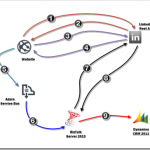
by Rene Brauwers | Apr 8, 2013 | BizTalk Community Blogs via Syndication
Note: Please be advised, this post most likely contains grammar mistakes I am sorry for that but I was in a hurry and wanted to share this with you all. Anyway; enjoy…
there was this BizTalk Integrator who was wondering how hard it would be to get LinkedIn profile information and store this in Microsoft Dynamics CRM 2011. He didn’t waste a lot of time and within no time he produced a diagram showing on a high level how he intended to tackle this issue.
-
Redirect user to LINKEDIN to get Authorization Code.
-
Authorization code is send back.
-
Request OAUTH 2.0 Access Token using obtained authorization code
-
OAUTH Access token is send back.
-
Establish Service Bus Connection. Create a Topic, Subscription and Filters if they don’t exists. Create message containing OAUTH Access token and set brokered message properties. Once done publish message.
-
BizTalk retrieves message from Topic Subscription.
-
BizTalk creates a GET Request including the OAUTH Token and sends it to the LinkedIn api to request the user’s information.
-
BizTalk receives a response from LinkedIn, and creates a new Atom Feed message containing the Contact Properties required to add a new contact in CRM
-
BizTalk sends a POST request to the CRM 2011 XRMServices/2011/OrganizationData.svc/ContactSet/ endpoint such that a new Contact is created
Okay all kidding aside; in this blog post I will dive deeper in to the above mentioned scenario, and will highlight the ins-and-outs as mentioned in steps 1 to 9. So let’s get started.
For all those, not interested in reading about it; but rather want to see the pre-recorded demo. Click here
One of the first challenges we have to tackle consist of obtaining a token from LinkedIn which allows us to perform authorized requests against a certain user profile. In English; in order to get LinkedIn profile information we need to acquire approval from the profile owner. Once we have obtained this permission we need to obtain an OATH 2.0 token which can then be used to authorize our requests to the LinkedIn API.
So how did I solve this ‘challenge’, well I build this small website based on MVC 4* and hosted it for free in Azure. This website uses the default MVC 4 template, and all I did is change some text and added a new controller and subsequent view. The controller, which I gave a self-explanatory name ‘LinkedInController’ takes care of all logic required (getting the OAUTH token and sending it so Windows Azure Service Bus).
Read all about MVC here, and in order to learn more about MVC and other cool stuff go to Pluralsight)
Below a more detailed overview, on how I took care of steps 1 to 4.
Note: I gathered the information on how to authenticate using OAUTH 2.0 from this page
1) Obtaining profile user permission.
On the default action (Index) in my case, I perform a good-old fashioned redirect to a LinkedIn site in order to obtain the user’s authorization (permission) to query his/hers LinkedIn profile. On this site the user is presented with the following screen.
2) Obtaining linkedIN’s authorization code.
Once the user has allowed access; he or she will be redirected back to the mvc website. This redirection request from LinkedIn contains a Authorization_Code parameter and points to a specific Action within the LinkedIn Controller.This action will extract the Authorization Code and this code will be stored internally.
3) Request OATH 2.0 token.
Next a HTTP Post to the LinkedIn API will be executed, containing the users authorization code and some other vital information
4) Process JSON response.
As a result we retrieve a JSON response which is serialized back into a custom object.
5) Publish message to windows azure service bus.
Once we’ve filled out custom object, I send it to a custom build class*, which then sends this object to a Windows Azure Topic.
* The custom class I’ve build is my own implementation of the REST API for creating TOPICs, Subscriptions, Filters and sending messages to Windows Azure Service Bus (see Service Bus REST API Reference). I’ve build this class a while back and the main reason I;’ve build it, is such that I can reuse it in my Demo Windows Phone Apps and Demo Windows Store Apps). I will not list the code here, however if you are interested just send me an email and I’ll send it to you
The above mentioned class requires that some specific information is passed in, this is explained below
Payload
The first required parameter is of type Object and should contain the message object which is to be sent to service bus.
Brokered message Properties
This parameter contains the key and value pairs adding additional context to the message send to service bus. In my demo I’ve added the following key value pairs to the message. The importance of these properties will be made clear in a little while.
Source=linkedIN
Method=select
Object=personalData
Auth=[DYNAMIC]
Note: Auth will be replaced in code with the actual OAuth 2.0 token received earlier and is added to the context of the message. Later on this is used by BizTalk (but more on this later)
Service bus name space
One of the required parameters is the service namespace which is to be used. In my demo I created a namespace called brauwers
A service namespace provides a scoping container for addressing Service Bus resources within your application.
Service bus Management Credentials
Two other parameters which are required, consist of the so-called issuer-name and issuer-token. These credentials are required if we want to perform actions on the service bus resource like (posting messages, or performing management operations). My component requries that you supply the owner (or full access) credentials as this component will try to perform some management operations (creating subscriptions) which needs these elevated privileges
Service bus Topic name
This parameter should consist of the name of the Topic to which the message will be published. In my demo I’ve chosen the value “SocialAccessTokens”.
Note: in case the topic does not exists the custom class will create it (hence the reason we need to use an issuer who has elevated (create) privileges
Service bus Topic subscription
This parameter holds the desired topic subscription name, which we want to create. In my demo I’ve chosen the value “LinkedINSubscription”
Note: Eventually a filter will be added to this subscription, such that messages matching a this filter or rule (see brokered message properties mentioned earlier) will be ‘attached’ to this subscription. The importance of this, will be made clear further down in this blog post when we will explain how BizTalk is configured). On another note; in case this subscription does not exist a the custom class will create it (hence the reason we need to use an issuer who has elevated (create) privileges.
Service bus Topic Filter name
This parameter contains the name to use for the filter, which will be attached to the topic subscription.
Service bus Topic Filter expression (Sqlfilter)
This parameter is actually pretty important as this parameter defines the rule which applies to the subscription it is attached to. The filter I used in my example –> Source = ‘linkedIN’ (keep in mind that we set a brokered message property earlier containing these values)
Note: the filter in my example should be interpreted as follows: messages send to the topic (SocialAccessTokens) which contain a brokered message property key named source, and of which the value matches the string “linkedIN” should be ‘attached’ to the subscription “LinkedINSubscription”.
Well the previous steps; ensured that a message containing the OAUTH 2.0 token, required to perform LinkedIn profile requests on behalf of the profile owner. The next steps should result in a new contact in Dynamics CRM 2011 based upon the data retrieved from LinkedIn. These steps involve BizTalk and some of it’s ‘new’ (or let’s reformulate this: out of the box) capabilities, consisting of the SB-Message adapter and the WCF-WebHttp Adapter.
So let’s get started.
6) Setting up BizTalk such that is connects to windows azure service bus.
At this point a message has been delivered to a Windows Azure Service Bus topic. However now we need to pull this message into BizTalk and for this to work we need to perform a few steps like
- a) defining a property schema used to capture the custom brokered message properties.
- b) define a schema which reflects the message send to windows azure service bus
- c) deploy the artifacts
- d) configure a receive port and location to get the service bus message(s) in BizTalk
These steps will be explained further below
Defining a property schema used to capture the custom brokered message properties.
Note: Before proceeding ensure you’ve created a new solution and BizTalk project and don’t forget to sign it with a strong key and give it an application name.
In step 5; we added a few custom properties to the message context consisting of the keys “Source,Method,Object and Auth” . In my example I want to use these properties as Promoted Properties within BizTalk, such that I can do some nice stuff with them (more about this in step 7). So in order to cater for this we need to create a new Property Schema in BizTalk and all this schema needs to contain are elements which are named exactly like the brokered message property key names.
Define a schema which reflects the message send to windows azure service bus
In order for BizTalk to recognize a message it’s message definition needs to be known internally. In English; if we want to work with the message as send to windows azure service bus in BizTalk, we need to ensure that BizTalk can recognize this message and thus we need to define. How this is done is explained below
- In my example I send a message to the service bus; this message is actually a representation of an internal defined class. This class is defined as mentioned below:
- So how do we translate this message to a BizTalk Schema? Well we have a few options, and I’ll use the not so obvious approach and that’s the manual approach. In order to do so, we need to create a new schema in BizTalk which has the following properties and structure:Target Namespace should match the DataContract Namespace, thus in my case : http://brauwers.nl/socialauthenticator/linkedin/v1.0/
The Main Root should match the class name, thus in my case :ApiAccessInformation
The main root should contain the following elements, all of them of type string
1) apiName
2) apiClientId
3) apiClientSecret
4) apiAccessScope
5) authorizationKeyThe end result should look like depicted in the image below
Deploy the artifacts
So far so good, but first let’s deploy the BizTalk project, and once it is deployed we can go ahead and start configuring it. (I named my BizTalk Application CRM2011)
Set up BizTalk Receive Port and Receive Location
So far so good, but now we need to put everything together such that we can configure BizTalk to read the Service Bus Topic Subscription and process any messages published to it. How this is done is explained below.
- Go to your just deployed BizTalk Application and create a one-way receive-port and name it appropriately.
- Created a new receive location, choose the SB-Messaging adapter, select your receive host and select the xml_receive pipeline component.
- Configured the SB-Messaging adapter. Enter the appropriate subscription url. In my case this would be: sb://brauwers.servicebus.windows.net/socialaccesstokens/subscriptions/LinkedINSubscription
sb://[NAMESPACE].servicebus.windows.net/[TOPIC_NAME]/subscriptions/[SUBSCRIPTION CONTAINING MESSAGES]
- Fill out the required authentication information, consisting of
the Access Control Service uri and a valid Issuer Name and Issuer Key
- Select the property schema to use such that the Brokered Message Properties defined earlier are treated as Promoted Properties within BizTalk.
- Press OK
7) Setting up BizTalk such that the LinkedIn API can be queried.
At this point we’ve set up BizTalk such that it can retrieve the messages published to windows azure service bus and tread the brokered message properties as Promoted properties. This section will now list and explain the next steps which are needed in order to query the LinkedIn API using the wcf-webhttp adapter.
Creating a new send port leveraging the new wcf-webhttp adapter
So how do we configure the wcf-webhttp adapter such that we can send a GET request to the linkedIn API, well the steps below will show how this is achieved.
- Create a new static solicit-response port and name it appropriately, choose the WCF-WebHttp adapter, choose your prefered send handler and select XML_Transmit as Send Pipeline and XML_Receive as Receive Pipeline
- Now click on configure, such that we can configure the WCF-WebHttp adapter.
- First configure the Endpoint address; I’ve used https://api.linkedin.com/v1/people
- Now we set the HTTP Method and URL Mapping, for this I use the BtsHttpUrlMapping element, which contains an operation method which is set to GET and the rest of the Address Uri which consists of a list of profile fields we want to select and an oauth2 access token which value we will set using variable mapping (step 5 below)
- In our BtsHttpUrlMapping we have set a dynamic parameter which was named {Auth}. The value we want to assign to this, will be the oAuth 2.0 token which is available to us as a promoted property (see explanation step 6 “Setting up BizTalk such that is connects to windows azure service bus“). So for Propery Name we select the element name containing the promoted propery value (in my case Auth) and for property namespace we enter the namespace name of our created property schema.
- Once done press OK.
- Now select the security tab and ensure that the security mode is set to Transport and the Transport client credential type is set to NONE
- Now go to the Messages Tab and ensure that the following Outbound Http Headers are set
Accept: application/atom+xml;
Content-Type: application/atom+xml;charset=utf-8
Accept-Encoding: gzip, deflate
User-Agent: BizTalk
- Make sure that the outbound message is surpressed, by indicating the GET verb-name
8) Dealing with the response message received from LinkedIn.
Well at this point we have send a GET request to linkedIn, however we haven’t set up the logic yet to cater for processing the response message send back to BizTalk by the LinkedIn API. So let’s dive in to it straight away.
Figuring out the response format from LinkedIn
In order to figure out the response message which is sent back to BizTalk, I have used Fiddler and composed a GET request as it would be sent by BizTalk.
- Open fiddler, and go to the compose tab, and use the following Uri, and replace [TOKEN] with the OAUTH token (note: you can get your token by going to the web application, but be aware if you allow access to your profile, you will be part of my DEMO and as a result your profile information will be stored in my Demo CRM environment )
https://api.linkedin.com/v1/people~:(first-name,last-name,email-address,date-of-birth,main-address,primary-twitter-account,picture-url,headline,interests,summary,languages,skills,specialties,educations,certifications,courses,three-current-positions,three-past-positions,following,job-bookmarks,phone-numbers,bound-account-types,twitter-accounts,im-accounts)?oauth2_access_token=[TOKEN]
- Add the following request headers
Accept: application/atom+xml;
Content-Type: application/atom+xml;charset=utf-8
Accept-Encoding: gzip, deflate
User-Agent: BizTalk
- Press Execute, and double click on the 200 Response, and select the RAW tab
- Copy and past the response message, and store it as an xml file
- Now go back to your BizTalk Solution and right click in your project and select –> Add new generated item)
- Select Generate Schema
- Select Well-Formed XML and browse to your saved XML file containing the response and press OK
- A new schema should be created and it should look similar to the one displayed below
9) Transforming the LinkedIn Profile RESPONSE and constructing a CRM POST request.
Well at this point we have the response definition, and now we are ready for constructing our POST request which eventually will ensure that we store the data in CRM. So let’s get started with these final pieces.
Figuring out the request message structure needed for inserting data into CRM
In order to figure out the request or payload message which is sent as body in the POST request to CRM, I have used this CRM Codeplex project CRM ODATA Query Designer Below the steps I performed to obtain the correct XML structure (note you need to have installed the codeplex project)
- Open up CRM in your browser and select the CRM Odata Query Designer
- Select ContactSet
- Press Execute and switch to the results (ATOM) tab
- Now look for the first ID and copy the url
- Copy this url in your browser and then select source
- Copy the result xml, and store it locally
- Open the xml file and let’s clean it up, such that only those fields are left which matter to you. See below my cleaned-up xml structure (please note the elements named new_ ,these are custom fields I’ve added)
- Now open up your BizTalk Solution, right click and select the “Add new generated item” like you did before and generate a schema using the well-formed xml.
- An xsd schema has been created, and it should look similar to the one depicted below. Note that I manually added the min and max occurance
Create a BizTalk Mapping which creates the CRM Insert Request
At this point we can create a mapping between the LinkedInResponse message and the CRM Insert message; I’ve done so and named this map “LinkedInPersonResponse_TO_AtomEntryRequest_CrmInsert.btm”
Build the BizTalk solution and Deploy
Now that we have all artifacts ready, we can deploy our BizTalk Solution once again and finish up the last part of our BizTalk configuration.
Creating a new send port leveraging the new WCF-WebHttp adapter to send a POST request to CRM
Our final step, before testing, consists of adding one last send port which leverages the WCF-WebHttp adapter once more; but this time we will be performing a HTTP POST to the crm endpoint (..XRMServices/2011/OrganizationData.svc/ContactSet/) which will result in a new contact record in CRM 2011. Below I’ll show you how to configure this last sendport.
- Create a new static One-Wayport and name it appropriately, choose the WCF-WebHttp adapter, choose your prefered send handler and select XML_Transmit as Send Pipeline
- Now click on configure, such that we can configure the WCF-WebHttp adapter.
- First configure the Endpoint address, which should point to an address ending on OrganisationData.svc/ContactSet .The full endpoint I’ve used is http://lb-2008-s07/Motion10/XRMServices/2011/OrganizationData.svc/ContactSet/
- Now we set the HTTP Method and URL Mapping, this is pretty straightforward as we only have to add the verb POST.
- Now select the security tab and ensure that the security mode is set to TransportCredentialOnly and the Transport client credential type is set to NTLM
- Now go to the Messages Tab and ensure that the following Outbound Http Headers are set
User-Agent: BizTalk
Content-Type: application/atom+xml
- Once done press OK
- Now select the outbound maps section, and select the map you’ve created and deployed earlier.
- Last but not least, add a Filter, stating “BTS.MessageType = person” such that the we can route the LinkedIn Response message (Person) to this sendport.
- At this point, we are done and we can now start the application and see if everything works.
Note: in order to be able to add records to CRM, you need to ensure that you’ve added the Host Intance User Account used for the selected Send Handler in CRM and granted this account the correct permissions. Failure doing so, will result in a 400 Bad Request which initially will throw you off.
Below I’ve added a few screenshots
The account svc-bts trustetd is the account used by the LowLatency_Host which I use to connect to the XRM service from CRM.
Subsequently I’ve created an account in CRM2011 for this user
and added this account (for testing purposes) to the System Administrator role.
Click Here to see a video showcasing above mentioned scenario