Date and Time functions are used to perform a variety of operations over Dates, such as retrieving the current date and time or adding dates, etc. If you come from the BizTalk Server background or are migrating BizTalk Server projects, they are the equivalent of Date/Time Functoids inside BizTalk Mapper Editor.
Available Functions
The Date and Time functoids are:
Add days: Adds a positive or negative number of days to the specified timestamp. Returns a timestamp that’s respectively later or earlier than the specified timestamp.
Add DayTime to Date: Adds a positive or negative DayTime duration to the specified Date value (xs:date). Returns a Date that’s respectively after or before the specified Date.
Add DayTime to DateTime: Adds a positive or negative DayTime duration to the specified DateTime value (xs:dateTime). Returns a DateTime that’s respectively after or before the specified DateTime.
Add DayTime to Time: Adds a positive or negative DayTime duration to the specified Time value (xs:time). Returns a Time that’s respectively after or before the specified Time. Durations that wrap around past midnight also return an earlier Time.
Add YearMonth to DateTime: Adds a positive or negative YearMonth duration to the specified DateTime value (xs:dateTime). Returns a DateTime that’s respectively after or before the specified DateTime.
Adjust Date: Adjusts the specified Date value (xs:date) to the current or dynamic time zone.
Adjust DateTime: Adjusts the specified DateTime value (xs:dateTime) to the current or dynamic time zone.
Adjust Time: Adjusts the specified Time value (xs:time) to the current or dynamic time zone.
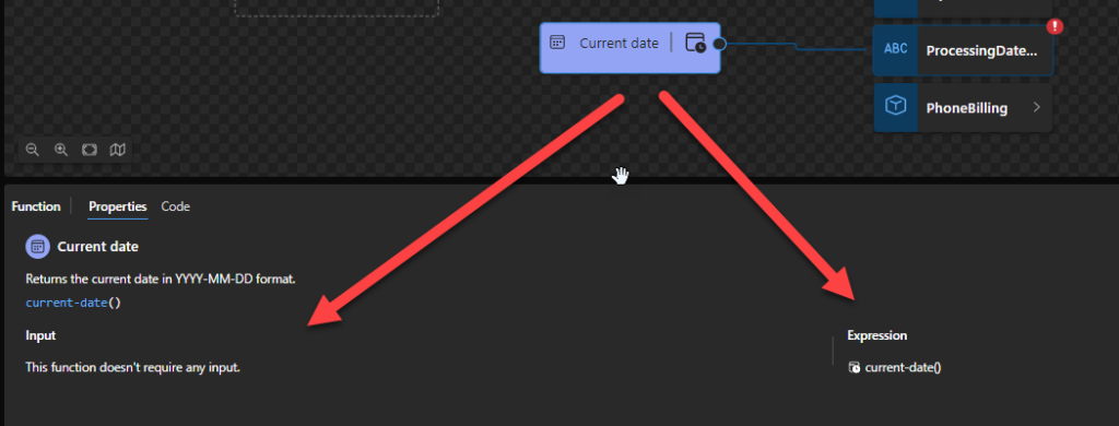
Current date: Returns the current date in YYYY-MM-DD format.
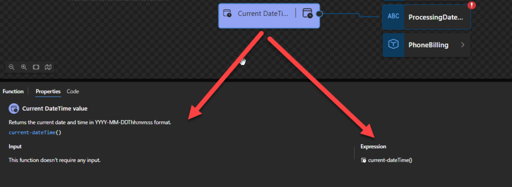
Current DateTime value: Returns the current date and time in YYYY-MM-DDThh:mm:ss format.
Current time: Returns the current date and time in YYYY-MM-DDThh:mm:ss format.
DateTime: Creates and returns a DateTime value based on the specified Date and Time.
Day from Date: Returns the day from the specified Date value (xs:date).
Day from DateTime: Returns the day from the specified DateTime value (xs:dateTime).
Equal Date: Returns true or false based on whether the specified Date values are equal.
Equal DateTime: Returns true or false based on whether with the specified DateTime values are equal.
Equal Day: Returns true or false based on whether the specified Day values (xs:gDay) are equal with the same starting time when the day values are in the same month and year.
Equal Month: Returns true or false based on whether the specified Month values (xs:gMonth) have the same starting time when the month values are in the same year.
Equal MonthDay: Returns true or false based on whether the specified MonthDay values (xs:gMonthDay) are equal with the same starting time when the day values are in the same year.
Equal Time: Returns true or false based on whether the specified Time values are equal.
Equal Year: Returns true or false based on whether the specified Year values (xs:gYear) have the same starting time.
Equal YearMonth: Returns true or false based on whether the specified YearMonth values (xs:gYearMonth) are the same.
Greater Date: Returns true or false based on whether the first Date value is later than the second Date value.
Greater DateTime: Returns true or false based on whether the first DateTime value is later than the second DateTime value.
Greater Time: Returns true or false based on whether the first Time value is later than the second Time value.
Hours from DateTime: Returns the hours from the specified DateTime value (xs:dateTime).
Hours from Time: Returns the hours from the specified Time value (xs:time).
Less Date: Returns true or false based on whether the first Date value is earlier than the second Date value.
Less DateTime: Returns true or false based on whether the first DateTime value is earlier than the second DateTime value.
Less Time: Returns true or false based on whether the first Time value is earlier than the second Time value.
Minutes from DateTime: Returns the minutes from the specified DateTime value (xs:dateTime).
Minutes from Time: Returns the minutes from the specified Time value (xs:time).
Month from Date: Returns the month from the specified Date value (xs:date).
Month from DateTime: Returns the month from the specified DateTime value (xs:dateTime).
Seconds from DateTime: Returns the seconds from the specified DateTime value (xs:dateTime).
Seconds from Time: Returns the seconds from the specified Time value (xs:time).
Subtract Dates: Returns the DayTimeDuration value (xs:dayTimeDuration) representing the elapsed time between the starting times for the specified Date values.
Subtract DateTimes: Returns a DayTimeDuration value (xs:dayTimeDuration) representing the elapsed time between the specified DateTime values..
Subtract DateTime from Date: Subtracts a positive or negative DayTime duration from the specified Date value (xs:date). Returns a Date that’s respectively before or after the specified Date..
Subtract DateTime from DateTime: Subtracts a positive or negative DayTime duration from the specified DateTime value (xs:dateTime). Returns a DateTime that’s respectively before or after the specified DateTime.
Subtract DateTime from Time: Subtracts a positive or negative Time duration from the specified Time value (xs:time). Returns a Time that’s respectively before or after the specified Time. A duration that wraps around past midnight also returns a later Time.
Subtract Times: Returns a DayTimeDuration value (xs:dayTimeDuration) representing the elapsed time between the specified Time values, which are treated as times on the same date.
Subtract YearMonth from Date: Subtracts a positive or negative YearMonth duration from the specified Date value (xs:date). Returns a Date that’s respectively before or after the specified Date.
Subtract YearMonth from DateTime: Subtracts a positive or negative YearMonth duration from the specified DateTime value (xs:dateTime). Returns a DateTime that’s respectively before or after the specified DateTime.
Time zone from Date: Returns the time zone from the specified Date value (xs:date).
Time zone from DateTime: Returns the time zone from the specified DateTime value (xs:dateTime).
Time zone from Time: Returns the time zone from the specified Time value (xs:time).
Year from Date: Returns the year from the specified Date value (xs:date).
Year from DateTime: Returns the year from the specified DateTime value (xs:dateTime).
Add days
This function states that it will add a positive or negative number of days to the specified timestamp. Returns a timestamp that’s respectively later or earlier than the specified timestamp.
To be documented in the future.
Add DayTime to Date
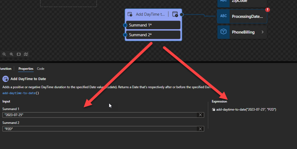
This function states that it will add a positive or negative DayTime duration to the specified Date value (xs:date). Returns a Date that’s respectively after or before the specified Date.
Behind the scenes, this function is translated to the following XPath function: xs:date(xs:date($arg1) + xs:dayTimeDuration($arg2))
The expression xs:date(xs:date($arg1) + xs:dayTimeDuration($arg2)) returns xs:date
Rules:
The $arg1 needs to be an xs:date in the following format yyyy-MM-DD or yyyy-MM-DDZ.
The $arg2 needs to be an interval in ISO 8601 format. ISO-8601 standard was created to elaborate crystal clear language to discuss dates and periods and avoid misinterpretation. Where Duration (“how long“) is represented with the format P[n]Y[n]M[n]DT[n]H[n]M[n]S, where n is a number.
The letters mean the representation of date and time:
P express that this is a period format and should be the first character;
Y for years; M for months; D for days;
T is the delimiter for the time;
H for hours; M for minutes; S for seconds;
Therefore PT means Period of Time.
PT20S: parses as 20 seconds.
PT15M: parses as 15 minutes (where a minute is 60 seconds).
PT10H: parses as 10 hours (where an hour is 3600 seconds).
P2D: parses as 2 days (where a day is 24 hours or 86400 seconds).
P2DT3H4M: parses as 2 days, 3 hours, and 4 minutes.
Sample:
The following Data Mapper transformation rule: add-daytime-to-date(“2023-07-25”, “P2D”) will be translated to {xs:date(xs:date(‘2023-07-25’) + xs:dayTimeDuration(‘P2D’))} and the return will be 2023-07-27
Add DayTime to DateTime
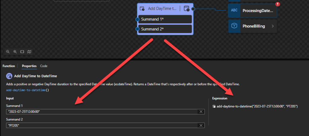
This function states that it will add a positive or negative DayTime duration to the specified DateTime value (xs:dateTime). Returns a DateTime that’s respectively after or before the specified DateTime.
Behind the scenes, this function is translated to the following XPath function: xs:dateTime(xs:dateTime($arg1) + xs:dayTimeDuration($arg1))
The expression xs:dateTime(xs:dateTime($arg1) + xs:dayTimeDuration($arg1)) returns xs:dateTime
Rules:
The $arg1 needs to be an xs:dateTime in the following format yyyy-MM-DDTHH:mm:ss or yyyy-MM-DDTHH:mm:ss-hh:mm.
The $arg2 needs to be an interval in ISO 8601 format. ISO-8601 standard was created to elaborate crystal clear language to talk about dates and periods and avoid misinterpretation. Where Duration (“how long“) is represented with the format P[n]Y[n]M[n]DT[n]H[n]M[n]S, where n is a number.
The letters mean the representation of date and time:
P express that this is a period format and should be the first character;
Y for years; M for months; D for days;
T is the delimiter for the time;
H for hours; M for minutes; S for seconds;
Therefore PT means Period of Time.
PT20S: parses as 20 seconds.
PT15M: parses as 15 minutes (where a minute is 60 seconds).
PT10H: parses as 10 hours (where an hour is 3600 seconds).
P2D: parses as 2 days (where a day is 24 hours or 86400 seconds).
P2DT3H4M: parses as 2 days, 3 hours, and 4 minutes.
Sample:
The following Data Mapper transformation rule: add-daytime-to-datetime(“2023-07-25T12:00:00”, “PT20S”) will be translated to {xs:dateTime(xs:dateTime(‘2023-07-25T12:00:00’) + xs:dayTimeDuration(‘PT20S’))} and the return will be 2023-07-25T12:00:20
Add DayTime to Time
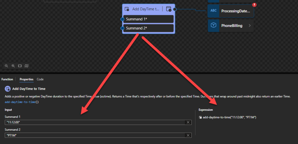
This function states that it will add a positive or negative DayTime duration to the specified Time value (xs:time). Returns a Time that’s respectively after or before the specified Time. Durations that wrap around past midnight also return at an earlier Time.
Behind the scenes, this function is translated to the following XPath function: xs:time(xs:time($arg1) + xs:dayTimeDuration($arg2))
The expressionxs:time(xs:time($arg1) + xs:dayTimeDuration($arg2)) returns xs:time
Rules:
The $arg1 needs to be an xs:time in the following format HH:mm:ss or HH:mm:ss-hh:mm.
The $arg2 needs to be an interval in ISO 8601 format. ISO-8601 standard was created to elaborate crystal clear language to discuss dates and periods and avoid misinterpretation. Where Duration (“how
The letters mean the representation of date and time:
P express that this is a period format and should be the first character;
Y for years; M for months; D for days;
T is the delimiter for the time;
H for hours; M for minutes; S for seconds;
Therefore PT means Period of Time.
PT20S: parses as 20 seconds.
PT15M: parses as 15 minutes (where a minute is 60 seconds).
PT10H: parses as 10 hours (where an hour is 3600 seconds).
P2D: parses as 2 days (where a day is 24 hours or 86400 seconds).
P2DT3H4M: parses as 2 days, 3 hours, and 4 minutes.
Sample:
The following Data Mapper transformation rule: add-daytime-to-time(“11:12:00”, “PT1M”) will be translated to {xs:time(xs:time(’11:12:00?) + xs:dayTimeDuration(‘PT1M’))} and the return will be 11:13:00
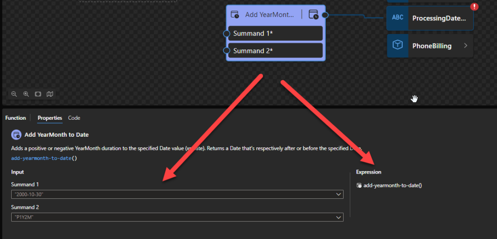
Add YearMonth to DateTime
This function states that it will Add a positive or negative YearMonth duration to the specified DateTime value (xs:dateTime). Returns a DateTime that’s respectively after or before the specified DateTime.
Behind the scenes, this function is translated to the following XPath function: xs:date(xs:date($arg1) + xs:yearMonthDuration($arg2))
The expression xs:date(xs:date($arg1) + xs:yearMonthDuration($arg2)) returns xs:date
Rules:
The $arg1 needs to be an xs:date in the following format yyyy-MM-DD or yyyy-MM-DDZ.
The $arg2 needs to be an interval in ISO 8601 format. ISO-8601 standard was created to elaborate crystal clear language to discuss dates and periods and avoid misinterpretation. Where Duration (“how long“) is represented with the format P[n]Y[n]M, where n is a number.
The letters mean the representation of date and time:
P express that this is a period format and should be the first character;
Y for years; M for months;
Therefore PT means Period of Time.
PT1Y: parses as 1 Year.
P1M: parses as 1 Month.
Sample:
The following Data Mapper transformation rule: add-yearmonth-to-date(“2023-07-26Z”, “P1M”) will be translated to {xs:date(xs:date(‘2023-07-26Z’) + xs:yearMonthDuration(‘P1M’))} and the return will be 2023-08-26Z.
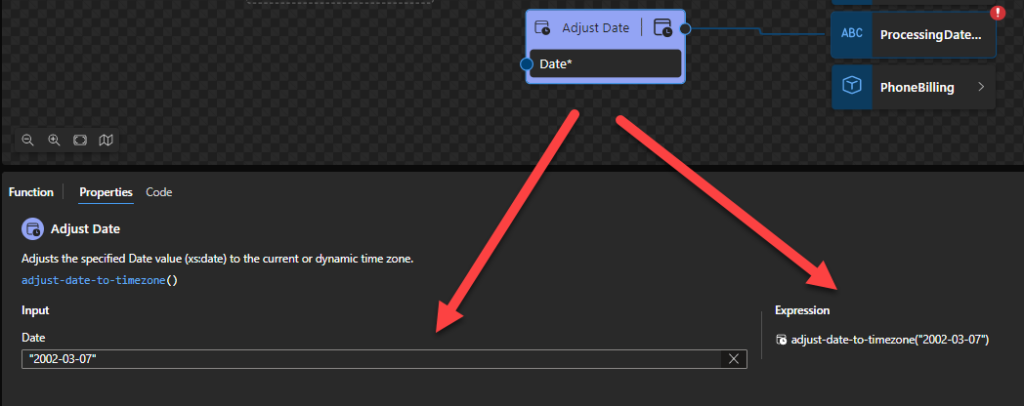
Adjust Date
This function states that it will adjust the specified Date value (xs:date) to the current or dynamic time zone, or to no timezone at all; the result is the date in the target timezone that contains the starting instant of the supplied date.
Behind the scenes, this function is translated to the following XPath function: adjust-date-to-timezone(xs:date($arg))
fn:adjust-date-to-timezone($arg as xs:date?) as xs:date?
Rules:
The $arg needs to be an xs:date in the following format yyyy-MM-DD or yyyy-MM-DDZ.
Sample:
The expression fn:adjust-date-to-timezone(xs:date("2002-03-07")) returns xs:date("2002-03-07-05:00").
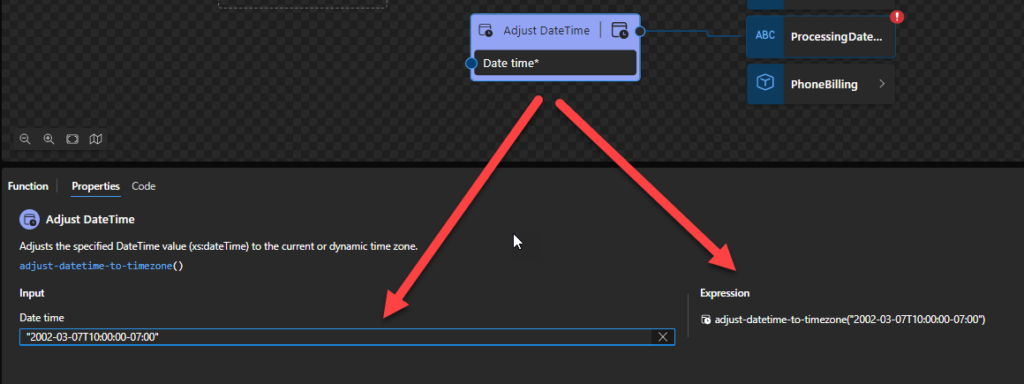
Adjust DateTime
This function states that it will adjust the specified DateTime value (xs:dateTime) to the current or dynamic time zone, or to no timezone at all.
Behind the scenes, this function is translated to the following XPath function: adjust-dateTime-to-timezone(xs:dateTime($arg))
fn:adjust-dateTime-to-timezone($arg as xs:dateTime?) as xs:dateTime?
Rules:
The $arg needs to be an xs:dateTime in the following format yyyy-MM-DDTHH:mm:ss or yyyy-MM-DDTHH:mm:ss-hh:mm.
Sample:
The expression fn:adjust-dateTime-to-timezone(xs:dateTime(‘2002-03-07T10:00:00-07:00’)) returns xs:dateTime(‘2002-03-07T12:00:00-05:00’).
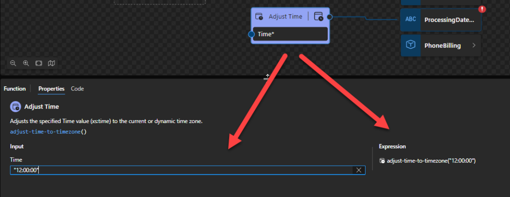
Adjust Time
This function states that it will adjust the specified Time value (xs:time) to the current or dynamic time zone, or to no timezone at all.
Behind the scenes, this function is translated to the following XPath function: adjust-time-to-timezone(xs:time($arg))
fn:adjust-time-to-timezone($arg as xs:time?) as xs:time?
Rules:
The $arg needs to be an xs:time in the following format HH:mm:ss or HH:mm:ss-hh:mm.
Sample:
The expression fn:adjust-time-to-timezone(xs:time(“10:00:00”)) returns xs:time(“10:00:00-05:00”).
Current date
This function states that it will return the current date in YYYY-MM-DD format. It depends on the implicit timezone (in many cases, if not all, it will include the offset).
Behind the scenes, this function is translated to the following XPath function: current-date()
fn:current-date() as xs:date
Rules:
Returns xs:date(fn:current-dateTime()). This is an xs:date (with timezone) that is current at some time during the evaluation of a query or transformation in which fn:current-date is executed.
The returned date will always have an associated timezone, which will always be the same as the implicit timezone in the dynamic context.
Sample:
For example, a call of fn:current-date() might return 2023-07-21+01:00.
Current DateTime value
This function states that it will return the current date and time in YYYY-MM-DDThh:mm:ss format.
Behind the scenes, this function is translated to the following XPath function: current-dateTime()
fn:current-dateTime() as xs:dateTimeStamp
Rules:
Returns the current dateTime (with timezone) from the dynamic context. This is an xs:dateTime that is current at some time during the evaluation of a query or transformation in which fn:current-dateTime is executed.
Sample:
For example, a call of fn:current-dateTime() might return 2023-07-26T23:43:42.392+01:00.
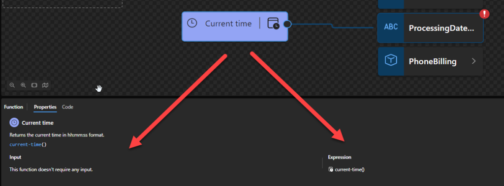
Current time
This function states that it will return the current date and time in YYYY-MM-DDThh:mm:ss format. It depends on the implicit timezone (in many cases, if not all, it will include the offset – 23:19:30.985+01:00).
Behind the scenes, this function is translated to the following XPath function: current-time()
fn:current-time() as xs:time
Rules:
Returns xs:time(fn:current-dateTime()). This is an xs:time (with timezone) that is current at some time during the evaluation of a query or transformation in which fn:current-time is executed.
The returned time will always have an associated timezone, which will always be the same as the implicit timezone in the dynamic context.
Sample:
For example, a call of fn:current-time() might return 23:19:30.985+01:00.
Stay tune for the second part of this blog post.
Hope you find this helpful! So, if you liked the content or found it useful and want to help me write more, you can buy (or help buy) my son a Star Wars Lego!
Author: Sandro Pereira
Sandro Pereira lives in Portugal and works as a consultant at DevScope. In the past years, he has been working on implementing Integration scenarios both on-premises and cloud for various clients, each with different scenarios from a technical point of view, size, and criticality, using Microsoft Azure, Microsoft BizTalk Server and different technologies like AS2, EDI, RosettaNet, SAP, TIBCO etc.
He is a regular blogger, international speaker, and technical reviewer of several BizTalk books all focused on Integration. He is also the author of the book “BizTalk Mapping Patterns & Best Practices”. He has been awarded MVP since 2011 for his contributions to the integration community.
View all posts by Sandro Pereira
In this blog post and tutorial, what we pretend to do is to create a Logic App, in this case, a Logic App Consumption, that sends reports through Log Analytics using an Azure Function to retrieve the data dynamically.
To do this, first, we need to understand a few things. First, what is theLog Analytics Workspace?
Log Analytics Workspace
A Log Analytics workspace is a unique environment for logging data from Azure Monitor and other Azure services, such as Microsoft Sentinel and Microsoft Defender for Cloud. Each workspace has its own data repository and configuration but might combine data from multiple services. It is also a centralized place where you can store, collect, and analyze data from various sources.
Think of it as a tool that helps you keep track of everything happening across your Azure environment. It allows you to perform advanced analytics and visualize data in real-time to help you identify and troubleshoot issues quickly. You can also use it to create custom queries and alerts, set up automation tasks, and integrate with other Azure services to get even more insights into your data. Overall, the log analytics workspace is a powerful tool that helps you stay on top of your Azure environment and ensure everything runs smoothly.
As explained above, we can create custom queries to retrieve data from Azure resources, such as Logic Apps, and how does that work?
First of all, you need to create a Log Analytics Workspace. For that:
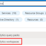
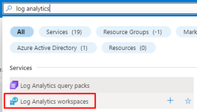
Search for Log Analytics in the search bar in Azure Portal and click on Log Analytics workspaces.
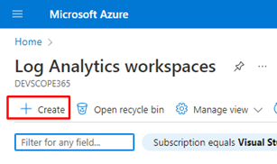
And next, click on Create.
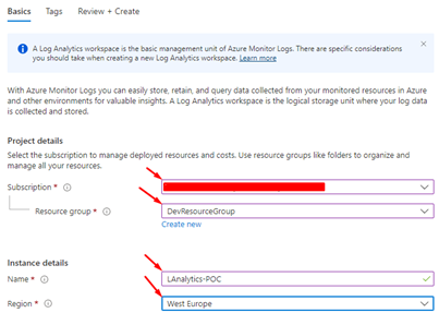
After this, populate the fields with the more appropriate information for your scenario, like the Name, Resource group, and Region, then click Review and Create.
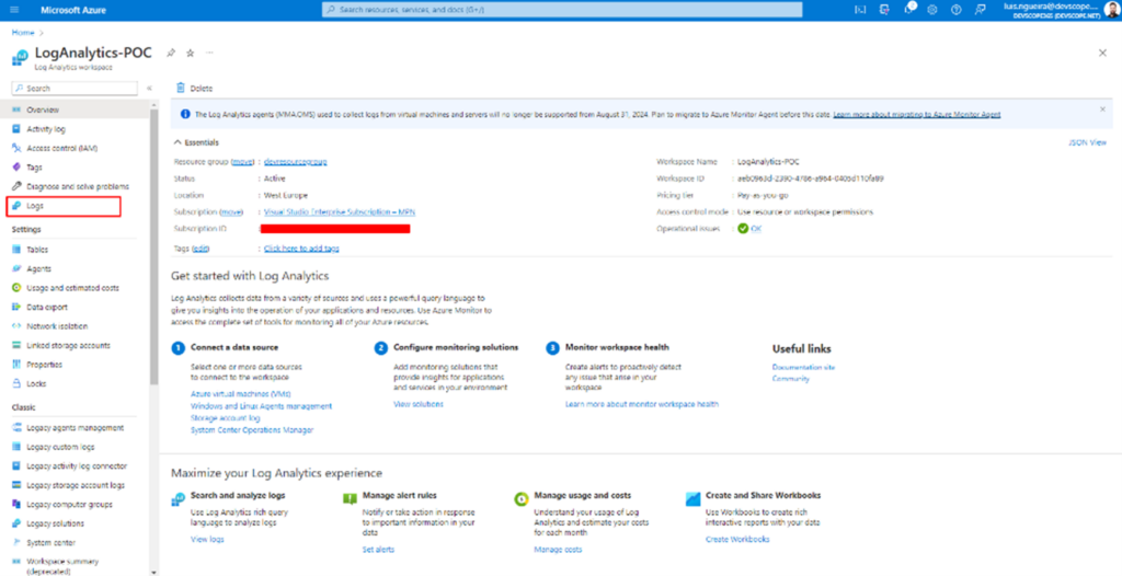
You should have this once the resource creation is finished, and this is your Log Analytics Workspace.
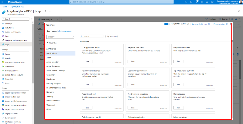
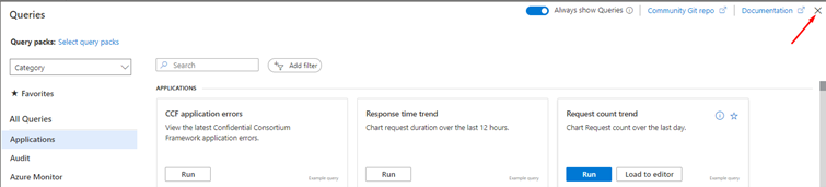
And if you click on Logs, it will open a panel that works via queries.
Some of them are already built-in queries, but if you click on the X.
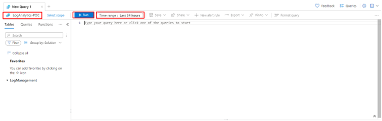
You will have a panel where you can write your own queries. And they work based on a scope. For example, you can apply this query to your resource group as you can apply your query to your Logic App. You also have a time range to apply the query to events that happened in the timespan you have defined.
But about queries on Azure Log Analytics, how do they work?And how to write them?
In Log Analytics on the Azure portal, queries are used to search and analyze the data that has been collected in the Log Analytics workspace. Think of queries as a way to ask questions about your data, such as, How many times did this event occur? or What was the average response time for this API? Once you write a query, the Log Analytics workspace will return the results in a table format, which you can use to gain insights and make data-driven decisions.
To write a query in Log Analytics on the Azure portal, you will use a query language called Kusto Query Language (KQL). And what is Kusto Query Language (KQL)?
Kusto Query Language (KQL) is a query language used in Azure Data Explorer, Azure Monitor, and Log Analytics for querying large datasets. KQL is a simple yet powerful language that allows you to search, analyze, and visualize data in a flexible way. KQL has a SQL-like syntax but also supports many features that are specific to Azure services, such as functions for querying JSON data, time-series data, and hierarchical data.
Some of the key features of KQL include:
Support for querying structured, semi-structured, and unstructured data
Built-in functions for working with dates, strings, arrays, and other data types
Support for aggregations, joins, and subqueries
Ability to query data in real-time
Integration with Azure services for data collection, storage, and visualization
KQL is a powerful tool that can help you gain insights and make data-driven decisions, especially when dealing with large datasets in Azure.
Here is an example of KQL:
AzureDiagnostics
| where Category == "LogicAppWorkflowRuntime" and WorkflowName == "my-logic-app"
| where OperationName == "WorkflowRunStarted" or OperationName == "WorkflowRunCompleted"
| project WorkflowName, OperationName, StartTime, EndTime, Status, Message
This query will:
Search for all events in the AzureDiagnostics table where the Category is LogicAppWorkflowRuntime, and the WorkflowName is my-logic-app.
It will then filter the results only to include events where the OperationName is either WorkflowRunStarted or WorkflowRunCompleted.
The project operator is used to select specific columns to include in the results. In this case, the query will return each event’s WorkflowName, OperationName, StartTime, EndTime, Status, and Message.
| is the pipe operator, which connects the different parts of the query together.
This query can help you monitor the performance and status of your Logic App by tracking when workflows are started and completed, as well as any associated error messages or status codes. You can run this query in Azure Log Analytics or Azure Monitor to gain insights into your logic app’s performance and troubleshoot any issues that arise.
How to configure a Logic App to send data to the Log Analytics workspace
So, now you have an idea of how it works, but, as we explained before, Azure Log Analytics collects the events from various Azure Resources, so to make this possible, we need to create a connection between the Resource we want to collect data from, and the Azure Log Analytics.
To do that, let’s create a Logic App, and in doing so, do not forget to use the same Resource Group and Region you have your Azure Log Analytics stored, and give the Logic App a name that makes sense to you and implement the desired business logic.
Do not forget: Start using Proper names from day one!
Or access to an existing Logic App.
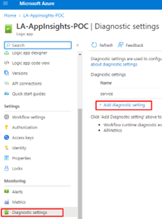
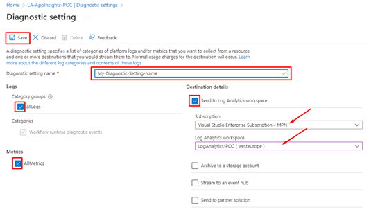
Next, click Diagnostic Settings and + Add diagnostic setting on your Logic App.
Give a name to your Diagnostic setting name, and check the boxes:
allLogs
AllMetrics
and Send to Log Analytics Workspace
Next, choose the subscription where your Log Analytics Workspace is created and choose your Log Analytics Workspace, the one we just created.
And from now on, this Logic App will send data to the Log Analytics!
Create a Logic App to create a report from Log Analytics Workspace
To do that, we need to:
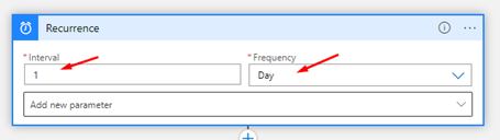
Create a new Logic App and add a Recurrence trigger and set the following configurations:
Choose the Interval as 1 and the Frequency Day
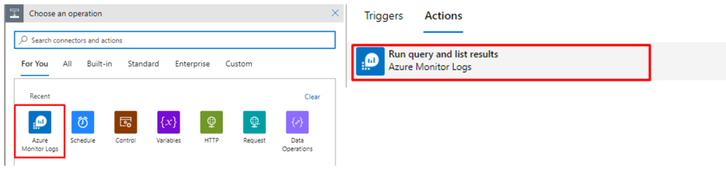
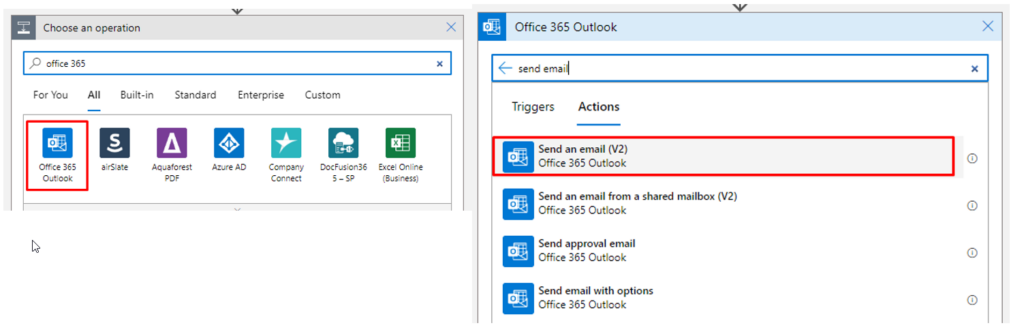
Next, choose the operation Azure Monitor Logs and the Action – Run query and list results.
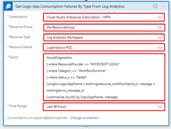
Next, you will have some fields to populate, like:
Subscription
Resource Group
Resource Type
Resource Name
Query
Time Range
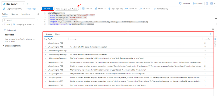
This is the query we will be using:
AzureDiagnostics
| where ResourceProvider == "MICROSOFT.LOGIC"
| where Category == "WorkflowRuntime"
| where status_s == "Failed"
| project LogicAppName = tostring(resource_workflowName_s), message = tostring(error_message_s)
| summarize count() by LogicAppName, message
In our case, we are dealing with a Logic App that has given us some errors already.
This is the raw output from the query if we run our logic app:
{
"statusCode": 200,
"headers": {
"Pragma": "no-cache",
"Transfer-Encoding": "chunked",
"Vary": "Accept-Encoding",
"Cache-Control": "no-store, no-cache",
"Set-Cookie": "ARRAffinity=eac69d9633b62a80172d43feba694263b4d9fccb8b9d953b364b8fc058f6e946;Path=/;HttpOnly;Secure;Domain=azuremonitorlogs-we.azconn-we-002.p.azurewebsites.net,ARRAffinitySameSite=eac69d9633b62a80172d43feba694263b4d9fccb8b9d953b364b8fc058f6e946;Path=/;HttpOnly;SameSite=None;Secure;Domain=azuremonitorlogs-we.azconn-we-002.p.azurewebsites.net",
"x-ms-request-id": "e8945bb2-f438-4ee9-9b22-58ae9971e462",
"Strict-Transport-Security": "max-age=31536000; includeSubDomains",
"X-Content-Type-Options": "nosniff",
"X-Frame-Options": "DENY",
"Timing-Allow-Origin": "*",
"x-ms-apihub-cached-response": "false",
"x-ms-apihub-obo": "false",
"Date": "Mon, 13 Mar 2023 12:47:12 GMT",
"Content-Type": "application/json; charset=utf-8",
"Expires": "-1",
"Content-Length": "2536"
},
"body": {
"value": [
{
"LogicAppName": "LA-AppInsights-POC",
"message": "",
"count_": 8
},
{
"LogicAppName": "LA-AppInsights-POC",
"message": "An action failed. No dependent actions succeeded.",
"count_": 17
},
{
"LogicAppName": "LA-AppInsights-POC",
"message": "The execution of template action 'For_each' failed: the result of the evaluation of 'foreach' expression '@{body('Get_Logic_App_Consumption_Failures_By_Type_From_Log_Analytics')?['value']} ------@{items('For_each_2')}---@{items('For_each_2')?['count_']}---@{items('For_each_2')?['message']}' is of type 'String'. The result must be a valid array.",
"count_": 7
},
{
"LogicAppName": "LA-AppInsights-POC",
"message": "Unable to process template language expressions in action 'DecodedContent' inputs at line '0' and column '0': 'The template language function 'decodeBase64' was invoked with a parameter that is not valid. The value cannot be decoded from base64 representation.'.",
"count_": 2
},
{
"LogicAppName": "LA-AppInsights-POC",
"message": "The 'from' property value in the 'table' action inputs is of type 'Object'. The value must be of type 'Array'.",
"count_": 1
},
{
"LogicAppName": "LA-AppInsights-POC",
"message": "The provided 'Http' action inputs are not valid. A request body must not be included for 'GET' requests.",
"count_": 1
},
{
"LogicAppName": "LA-AppInsights-POC",
"message": "Unable to process template language expressions in action 'Initialize_variable_2' inputs at line '0' and column '0': 'The template language function 'decodeBase64' expects one parameter: the string to decode from base64 representation. The function was invoked with '0' parameters. Please see https://aka.ms/logicexpressions#decodeBase64 for usage details.'.",
"count_": 1
},
{
"LogicAppName": "LA-AppInsights-POC",
"message": "Unable to process template language expressions in action 'Initialize_variable_2' inputs at line '0' and column '0': 'The template language function 'decodeBase64' was invoked with a parameter that is not valid. The value cannot be decoded from base64 representation.'.",
"count_": 1
},
{
"LogicAppName": "LA-AppInsights-POC",
"message": "The 'from' property value in the 'table' action inputs is of type 'String'. The value must be of type 'Array'.",
"count_": 1
},
{
"LogicAppName": "LA-Monitoring-Telemetry",
"message": "",
"count_": 2
},
{
"LogicAppName": "LA-Monitoring-Telemetry",
"message": "An action failed. No dependent actions succeeded.",
"count_": 3
},
{
"LogicAppName": "LA-Monitoring-Telemetry",
"message": "The 'from' property value in the 'table' action inputs is of type 'Null'. The value must be of type 'Array'.",
"count_": 1
}
]
}
}
If we use this same query in our Log Analytics Workspace, we get these results:
As you can see, we have a report of the Last 7 days with data including the Logic App Name, the error message, and the count.
This is useful in situations where you or your company or the project you are working on is dealing with a lot of data, and you need to know what Failed, where it Failed, and how many times it Failed. So, since we can query this information in the Log Analytics Workspace, we can do the same in our Logic App, as we explained before, using the Azure Monitor Logs and the Action – Run query and list results.
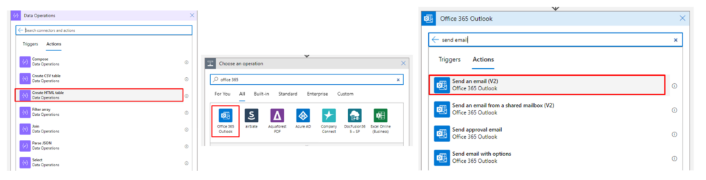
Now going back to our Logic app, we have two options, send this report as an HTML table as it is using a Data Operation – Create HTML Table, and then send an email with this information.
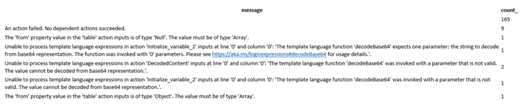
And what you will receive is something like this (in this example, we are not counting with the Logic App Name)
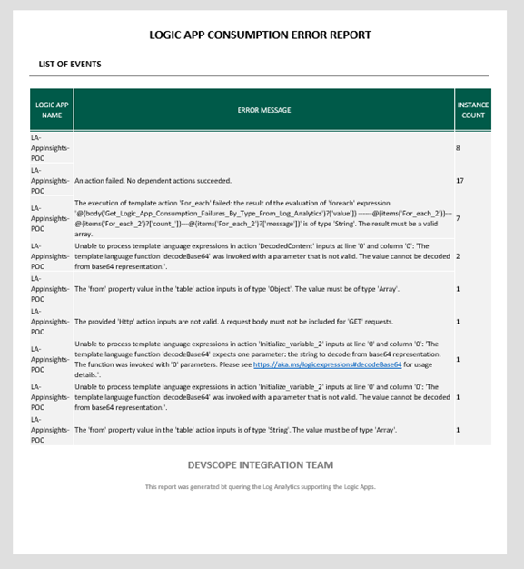
But this data delivery seems a bit old-fashioned, so why not create something more appealing? Something to be presented in the Body of an email like this:
And to achieve this, what we have done was to use an already HTML base document and an Azure Function to map the Rows into an HTML table. (we are not going to address this topic in this tutorial)
Finally, in our Logic App, we may want to validate if the query got results or if it is empty and then send an email with the report.
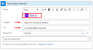
On the body of the email, add the Variable containing the HTML template (and the Azure Function call result), and add a subject and an email.
Save the Logic App once it is finished.
And now you will get the report from Log Analytics Workspace!
Remember that, for example, if you set the recurrence as daily and the query also is looking for events that have occurred in the last 24 hours, you might not have an email to present since the condition prevents it from sending the email if the Body is null, but this also means there are no flaws in your logic apps, which is always nice!
Thanks to my team member Luís Rigueira for helping me realize and implement this idea.
Hope you find this useful! So, if you liked the content or found it useful and want to help me write more content, you can buy (or help buy) my son a Star Wars Lego!
Author: Sandro Pereira
Sandro Pereira lives in Portugal and works as a consultant at DevScope. In the past years, he has been working on implementing Integration scenarios both on-premises and cloud for various clients, each with different scenarios from a technical point of view, size, and criticality, using Microsoft Azure, Microsoft BizTalk Server and different technologies like AS2, EDI, RosettaNet, SAP, TIBCO etc.
He is a regular blogger, international speaker, and technical reviewer of several BizTalk books all focused on Integration. He is also the author of the book “BizTalk Mapping Patterns & Best Practices”. He has been awarded MVP since 2011 for his contributions to the integration community.
View all posts by Sandro Pereira
One of the most ancient and common standards for message representation is using text files (Flat Files) like CSV (Comma Separated Values) or TXT files, many of which are custom-made for their systems. And do not be fooled and think these messages are outdated and rarely used. Still today, many existing integrations and new integrations are made based on Flat Files.
No matter if you are working with Logic Apps Consumption or Logic Apps Standard, there are only two ways to generate a Flat File Schema:
Using a BizTalk Server Visual Studio Project (Visual Studio 2019 or older, depending on the BizTalk Server version you are using), this is a good option if you have a BizTalk Server environment and if you are migrating BizTalk Server solutions.
Or using the Azure Logic Apps Enterprise Integration Tools. This is an add-in for the Integration Account project to support XML Schema creation, XML transform designer, and Flat File Schema generation for Visual Studio 2019.
In this blog post, we will address how to create a flat file schema using the Azure Logic Apps Enterprise Integration Tools – in this case, a CSV file – and how to process it using the Logic Apps Consumption. The biggest difference between using Logic App Consumption or Standard is that to process a flat file using Consumption, it is required to have an Integration Account, which is not needed in Standard.
How to create a Flat File Schema for a CSV file
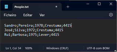
Normally, CSV files contain structured data so that a comma or semicolon separates individual items in the file, and each record is on a new line. In the image below, the CSV file contains five columns:
First name
Last name
Birth year
City
And Zip Code
and on each row, there is a person’s data.
We are going to use this sample as our example.
To create a flat file schema for this CSV file, we need to:
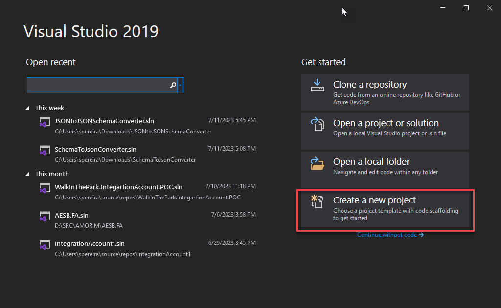
Open Visual Studio 2019 and create a new project by selecting Create a new project option.
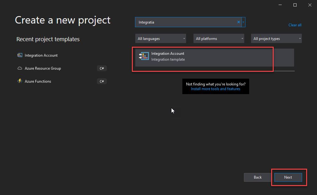
On the Create a new project window, search for the Integration Account template, select the Integration Account template, and click Next.
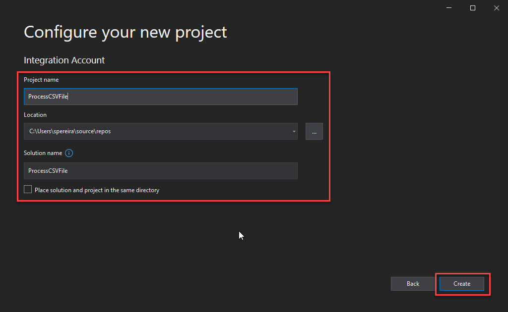
On the Configure your new project window, give a Project name and a Solution name and set the Location. Then click Create.
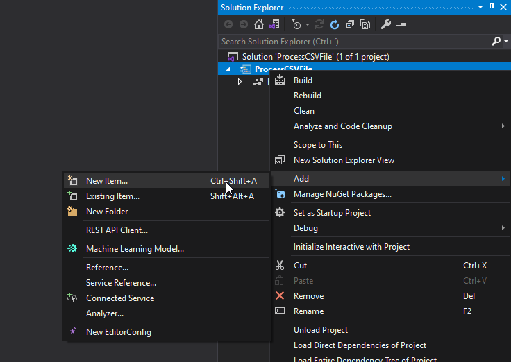
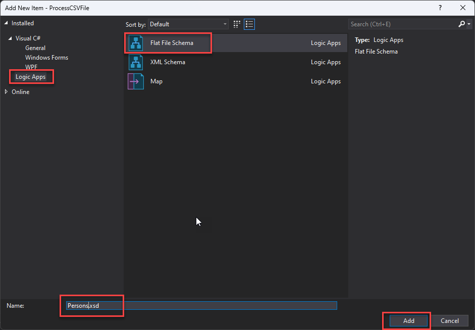
Once the Visual Studio project is created, right-click the project name and select the option Add > New Item…
On the Add New Item window, on the left tree, select Logic Apps and then select the Flat File Schema, give it a name, and click Add.
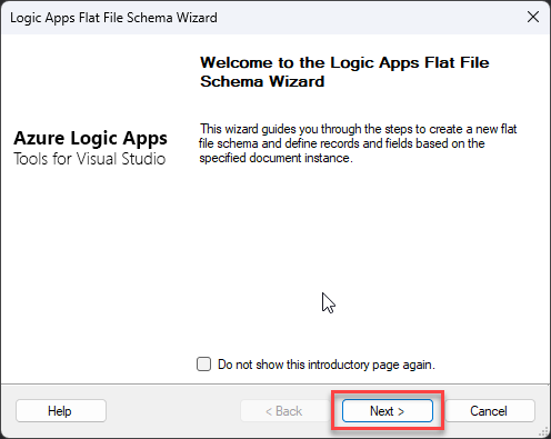
This will start the Logic Apps Flat File Schema Wizard. On the Welcome screen, click Next >.
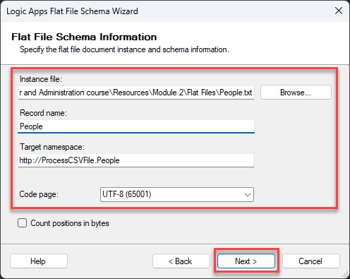
On the Flat File Schema Information screen, set the following configurations and then click Next >:
On the Instance file property, click the Browse button to locate the flat file from which the schema will be generated.
On the Record name property, give a name to define the root node name of your XML message—for example, People.
On the Target namespace property, set your desired namespace or leave the default.
On the Code page property, select UTF-8 (65001) from the drop-down selection list.
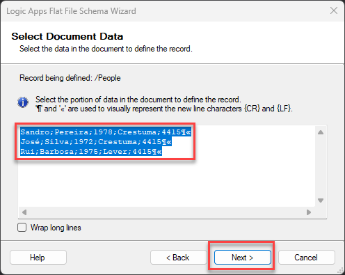
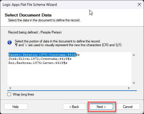
Because this is a small message on the Select Document Data screen, leave the default selected data and click Next >.
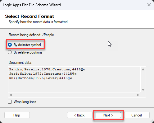
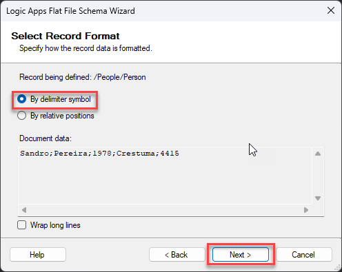
We will separate or define what separates a person on this first Select Record Format screen. And in this case, it is the new line. So, select the option By delimiter symbol and click Next >.
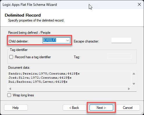
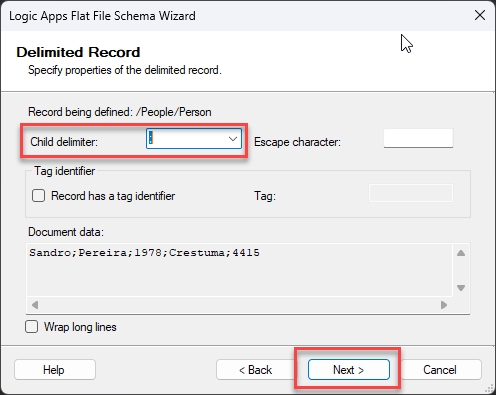
On the Delimiter Record screen, the child delimiter property is already defined to be the new line ({CR}{LF}), so leave the default configuration and click Next >.
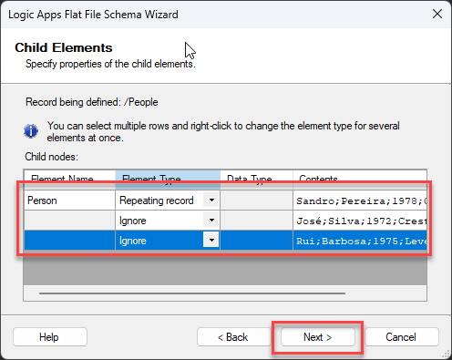
On the Child Elements screen, on the first line, set the following configuration:
Element Name: Person
Element Type: Repeating record
And on the rest of the lines, set the Element Type to Ignore since all lines represent the Person we will define on the first line. And then click Next >.
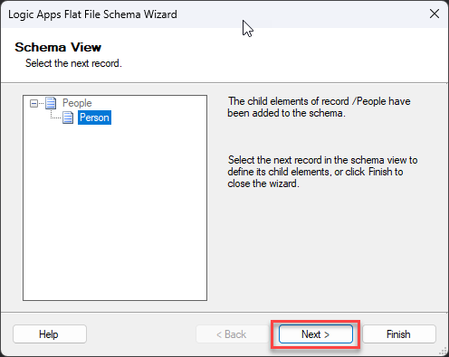
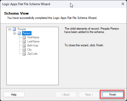
On the Schema View screen, you notice our Schema representation is being created. Click Next >.
Now, back to the Select Document Data screen, you notice that only the first line is automatically selected, excluding the new line character, and this is what we want. We will be defining the structure of the person object. Click Next >.
A semicolon separates this document, so in the Select Record Format screen, select the option By delimiter symbol and click Next >.
On the Delimiter Record screen, change the child delimiter property to a semicolon (;), and click Next >.
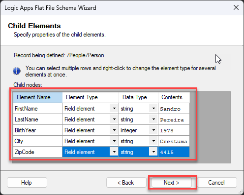
Now you notice that we have all fields separated in the Child Elements screen. Give the following configuration and click Next >.
FirstName (string)
LastName (string)
BirthYear (integer)
City (string)
ZipCode (string)
On the Schema View screen, you notice our Schema representation is finished. Click Finish.
And the Schema will open inside Visual Studio.
Now that we have our schema created, we need to upload it to our Integration Account – if you don’t have it, you need to create an Integration Account inside the Azure Portal. To do that:
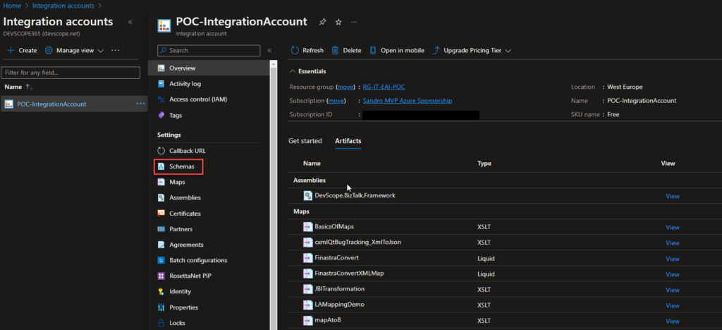
In the Azure Portal, access your Integration Account and select the Schemas option under Settings.
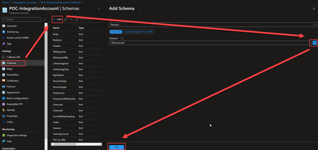
On the Schemas page, click in + Add and on the Add Schema panel on the Schema property, browse for the schema we just created and click Ok.
This will add the schema to your Integration Account, which can be used inside your Logic Apps.
Now we need to create a Logic App to process this CSV. To do that, we need to:
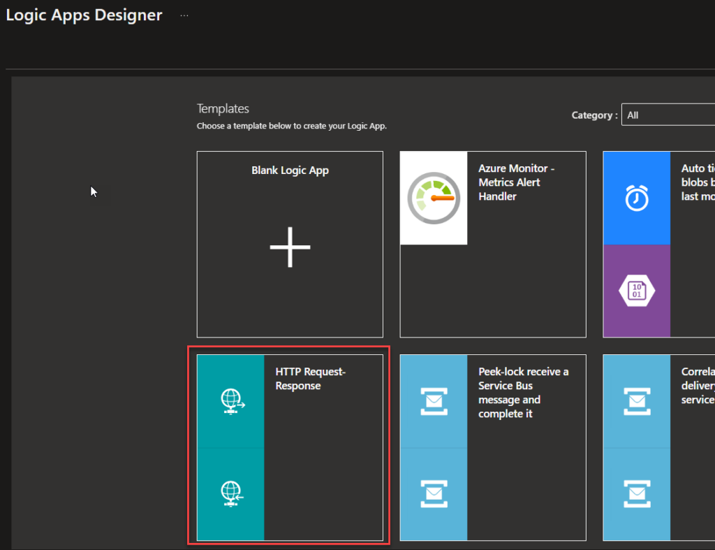
Create a Logic App and use the HTTP Request-Response template – of course, this can be adapted to your requirements.
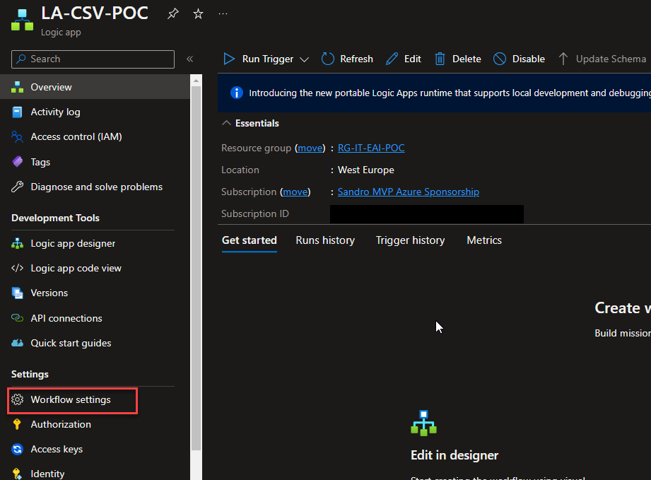
Once the Logic App design is loaded, click Save and return to your Logic App page. From there, click Workflow settings under Settings.
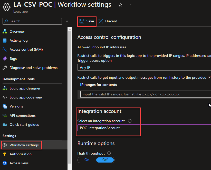
On the Workflow settings page, under the Integration account section, select the integration account in which we add our previous flat file schema on the Select an Integration account property. And click Save.
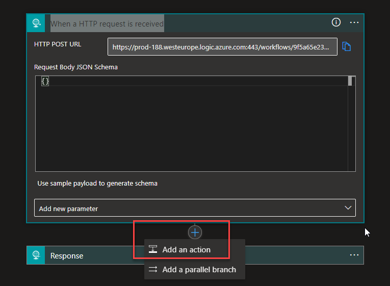
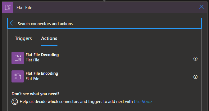
Now back to our Logic App designer. After the When a HTTP request is received trigger, select Add an Action.
On the Choose an operation panel, search for Flat File and then choose the Flat File > Flat File Decoding action.
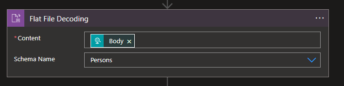
On the Flat File Decoding action, set the following configurations:
Content: Body from the When a HTTP request is received trigger.
Schema Name:Persons – the flat file we created earlier.
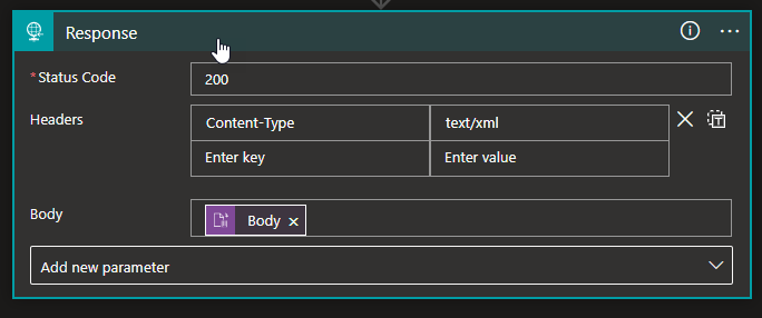
Now, select the Response action and set the following configurations:
Status Code: 200
Headers: Content-Type: text/xml
Body: Body from the Flat File Decoding action.
And finally, save the Logic App.
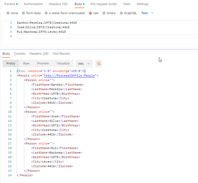
Now if we open Postman and send the following request, the expected response will be the same payload translated to XML, as you see in the picture below:
Hope you find this useful! So, if you liked the content or found it useful and want to help me write more content, you can buy (or help buy) my son a Star Wars Lego!
Author: Sandro Pereira
Sandro Pereira lives in Portugal and works as a consultant at DevScope. In the past years, he has been working on implementing Integration scenarios both on-premises and cloud for various clients, each with different scenarios from a technical point of view, size, and criticality, using Microsoft Azure, Microsoft BizTalk Server and different technologies like AS2, EDI, RosettaNet, SAP, TIBCO etc.
He is a regular blogger, international speaker, and technical reviewer of several BizTalk books all focused on Integration. He is also the author of the book “BizTalk Mapping Patterns & Best Practices”. He has been awarded MVP since 2011 for his contributions to the integration community.
View all posts by Sandro Pereira
We live in a REST era where JSON or XML is our text-based format default choice of text-based formats and widespread use by major corporations. However, one of the most ancient and common standards for message representation is using text files (Flat Files) like CSV (Comma Separated Values) or TXT files, many of which are custom-made for their systems. Do not be fooled and think these messages are outdated and rarely used. A good example is EDI messages, which are used extensively by large companies, so it is often necessary to transform text files into XML and vice versa.
Still today, many existing integrations and new integrations are made based on Flat Files.
What are Flat Files?
The standard definition states that a flat file is a collection of data stored in a two-dimensional database in which similar yet discrete strings of information are stored as records in a table. The table’s columns represent one database dimension, while each row is a separate record. Or in other words, it is a type of data storage file in which data is stored as plain text, often in a table-like structure with rows and columns. Each row represents a single record, while columns represent fields or attributes of the data. The information stored in a flat file is generally alphanumeric with little or no additional formatting. The structure of a flat file is based on a uniform format as defined by the type and character lengths described by the columns.
Flat files serve various purposes in software development, primarily for data storage, exchange, and processing tasks. They are widely used due to their simple structure, human readability, and ease of manipulation across different platforms and applications. For instance, flat files are commonly employed in data import and export operations, where applications or systems with diverse data storage mechanisms must communicate or transfer data.
A flat-file instance message is a text file that can contain three logical parts:
A header.
A body.
And a trailer.
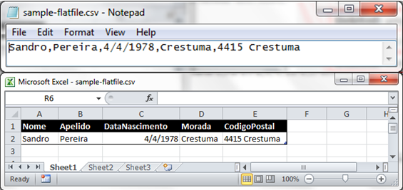
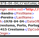
In that order. Of course, both the header and the trailer are optional. The following example shows a flat-file instance message consisting of all three parts, with the body in bold type:
Sandro Pereira Porto, Portugal PO,1,BOOK,4415 TRANS-1
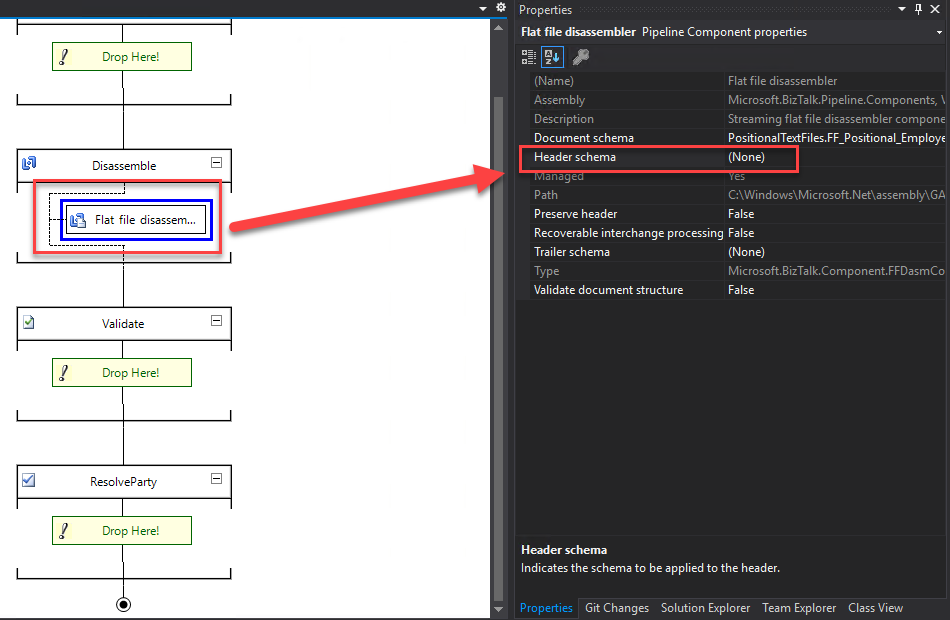
If you come from a Microsoft BizTalk Server background or if you are migrating a BizTalk Server project using these types of Flat-Files, you may know that the Flat file disassembler’s parsing allows you to specify:
The Header Schema in the Header schema design-time property of the flat file disassembler or the XMLNORM.HeaderSpecName message context property.
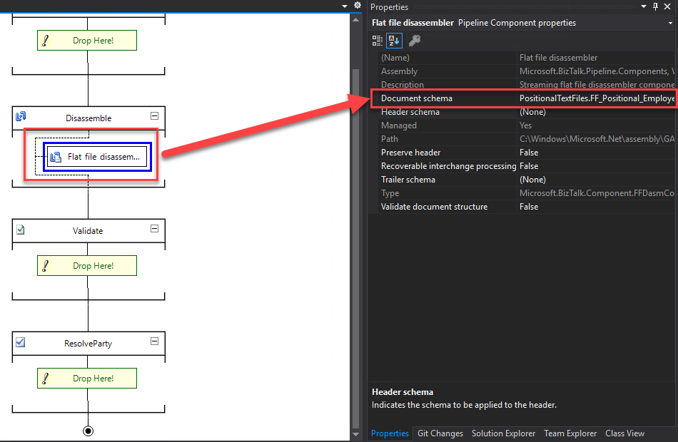
The Body Schema in the Document schema design-time property of the flat file disassembler or the XMLNORM.DocumentSpecName message context property.
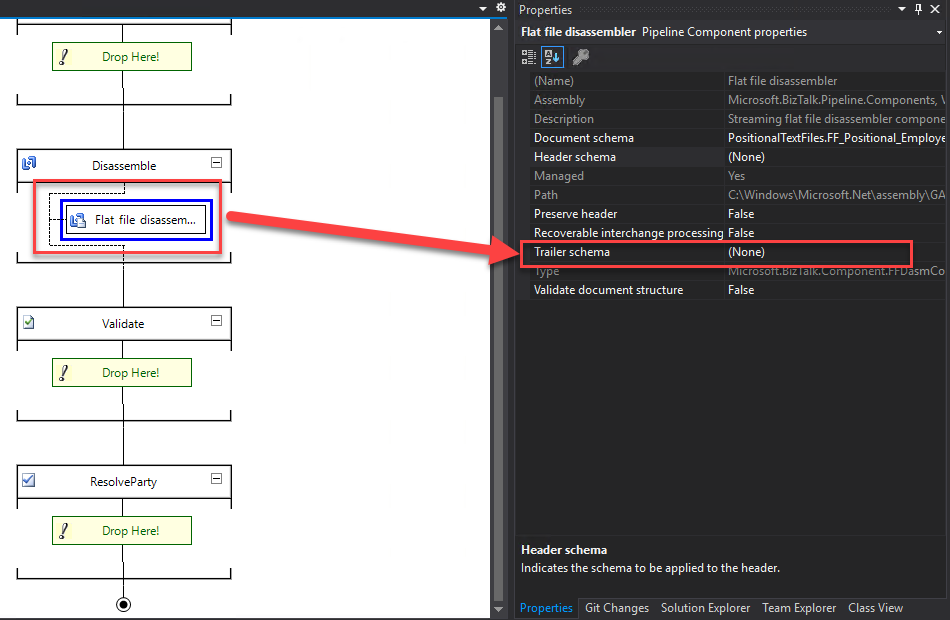
And the Trailer Schema in the Trailer schema design-time property of the flat file disassembler or the XMLNORM.TrailerSpecName message context property.
However, Logic Apps only supports Body Schemas. You cannot have different schemas for Headers, Bodies, and Trailers. You can still process these types of flat-files messages but in a different approach with a single Schema dividing what is a header, body and trailer in different records (structures).
Flat-File Schema Types
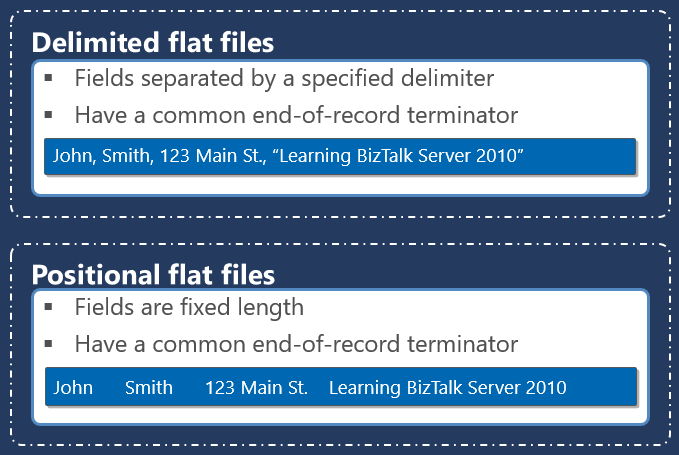
Within a particular part of a flat-file instance message, different data items are grouped into records, which themselves can contain sub-records and, ultimately, individual data items known as fields. These records and fields are distinguished from each other using one of two different basic methodologies.
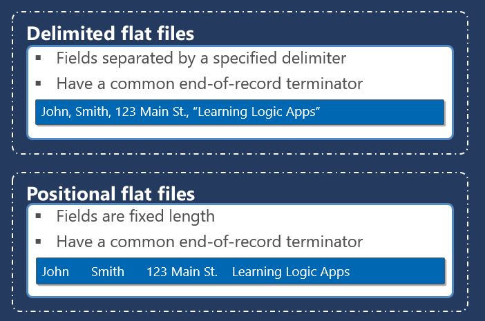
The first methodology, known as positional, defines each data item as a pre-established length, with pad characters being used to bring a shorter item of data up to its expected length.
The second methodology, known as delimited, uses one or more special characters to separate items of data from each other. This methodology avoids the need for otherwise superfluous pad characters. Still, it introduces some special considerations when the data itself contains the character or sequence of characters being used as a delimiter.
Positional Flat Files
Positional records within a flat-file instance message contain individual fields (items of data) that are each of a predefined length. The fields are parsed according to these lengths. For example, consider the following positional record from a flat-file instance message containing an id, country code, client name, and Country name:
01 PT Sandro Pereira Portugal
A reasonable definition for this record in a flat-file schema can be described as follows:
A positional record named Client contains the following fields:
An attribute named id that is left-aligned, three characters in length, with a zero character offset.
An element named countryCode that is left-aligned, three characters in length, with a zero character offset.
An element named name that is left-aligned, 37 characters in length, with a zero character offset.
An element named country that is left-aligned, and the length is until the end of the line.
Given these record and field definitions, the Flat file disassembler will produce the following XML equivalent of this record:
   PT
   Sandro Pereira
   Portugal
There are several considerations related to positional records that will affect how the record is parsed when received and constructed when sent, including:
The character used to fill the unused portion of each field, known as the pad character.
An optional tag within the record can be used to distinguish the record from other similar records. Tags usually occur at the beginning of the record but are allowable anywhere within it. Positional records can be defined to have a tag or not have a tag, but once defined, the tag must be present or not, based on the definition.
How data is justified within a fixed length field relative to the accompanying pad characters.
Positional records nested within other positional or delimited records.
Positional records with field lengths specified as a specific number of bytes rather than a specific number of characters.
Notes:
Suppose your flat file contains both delimited and positional records. In that case, you must set the Structure property of the root node to Delimited and the Structure property of subordinate record nodes to either Delimited or Positional as appropriate.
Fields in positional records have a limit of 50000000 characters.
Delimited Flat Files
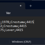
Delimited records within a flat-file instance message contain nested records and/or individual fields (items of data) that are separated by a predefined character or set of characters. The fields are parsed according to these separating delimiters. For example, consider the following delimited records from a flat-file instance message, which contain three client lines to add to our internal system hypothetically:
A reasonable definition for this record in a flat-file schema can be described as follows:
A delimited repeating record named Client with child delimiter {CR}{LF}
And delimited elements with child delimiter ;
firstName
lastName
birthYear
city
zipCode
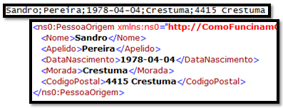
Given these record and field definitions, the Flat file disassembler produces the following XML equivalent of these records.
   Sandro
   Pereira
   1978
   Crestuma
   4415


...

...
There are several considerations related to delimited records that will affect how the record is parsed when received and constructed when sent, including:
The character or characters are used to override the interpretation of delimiters so that they are treated as part of the data.
An optional tag at the beginning of the record can be used to distinguish the record from other similar records.
How data is justified within fields with minimum lengths relative to the accompanying pad characters.
Positional records nested within other delimited records.
How data is justified within a fixed length field relative to its accompanying pad characters.
Preservation and suppression of delimiters when flat-file messages are received and sent.
Notes:
Suppose your flat file contains both delimited and positional records. In that case, you must set the Structure property of the root node to Delimited and the Structure property of subordinate record nodes to either Delimited or Positional as appropriate.
Delimited fields in flat files have a limit of 50000000 characters.
How do Logic Apps process the text files (Flat Files)?
When building a logic app workflow in Azure Logic Apps, you can encode and decode flat files using the Flat File built-in connector actions and a flat file schema for encoding and decoding. You can use Flat File actions in multi-tenant Consumption logic app workflows and single-tenant Standard logic app workflows.
Inside Logic Apps Consumption, Integration Account is required to store the flat-files schemas and use the Flat File built-in connector.
Inside Logic Apps Standard, there is no need for having an Integration Account since Schemas are supported built-in. However, if you desire, you can still use the Integration Account.
While no Flat File triggers are available, you can use any trigger or action to feed the flat-file content into your workflow. For example, you can use a built-in connector trigger, a managed or Azure-hosted connector trigger available for Azure Logic Apps, or even another app, like the Request built-in trigger or File System trigger.
Flat File Encoding action
The Flat File Encoding action allows you to convert an XML message into a flat file. Note that this action does not validate the incoming XML message. For that, you need to use the XML Validation action.
In Logic Apps Consumption, this action allows the following inputs:
The Content property, where you specify the XML message you want to encode to flat-file.
The Schema Name property is where you choose the flat-file body Schema or the Document schema.
If the schema list is empty, either your logic app resource isn’t linked to your integration account or doesn’t contain any schema files.
And then we have the following optional properties:
Mode of empty node generation, where we specify the mode to use for empty node generation with flat file encoding. Possible values are ForcedDisabled, HonorSchemaNodeProperty, or ForcedEnabled.
And XML Normalization allows you to enable or disable XML normalization in flat file encoding. Possible values are Yes or No.
In Logic Apps Standard, this action allows the following inputs:
The Content property, where you specify the XML message you want to encode to flat-file.
In the Source property, we select either LogicApp or IntegrationAccount as your schema source.
The Name property is where you choose the flat-file body Schema or the Document schema.
If the schema list is empty, either your logic app resource isn’t linked to your integration account, your integration account doesn’t contain any schema files, or your logic app resource doesn’t contain any schema files.
And then we have the following optional properties:
Mode of empty node generation, where we specify the mode to use for empty node generation with flat file encoding. Possible values are ForcedDisabled, HonorSchemaNodeProperty, or ForcedEnabled.
And XML Normalization allows you to enable or disable XML normalization in flat file encoding. Possible values are Yes or No.
Flat File Decoding action
The Flat File Decoding action allows you to convert a flat-file message into an XML message. Note that this action does not validate the outcome XML message. For that, you need to use the XML Validation action.
In Logic Apps Consumption, this action allows the following inputs:
The Content property, where you specify the flat-file message you want to decode to XML.
The Schema Name property is where you choose the flat-file body Schema or the Document schema.
If the schema list is empty, either your logic app resource isn’t linked to your integration account or doesn’t contain any schema files.
In Logic Apps Standard, this action allows the following inputs:
The Content property, where you specify the flat-file message you want to decode to XML.
In the Source property, we select either LogicApp or IntegrationAccount as your schema source.
The Name property is where you choose the flat-file body Schema or the Document schema.
If the schema list is empty, either your logic app resource isn’t linked to your integration account, your integration account doesn’t contain any schema files, or your logic app resource doesn’t contain any schema files.
Unlike BizTalk Server, where this Syntax Transformations or Data translation typically happens inside Receive or Send Pipelines. Inside Logic Apps, they happen inside our business process, aka Logic App using the Flat File connector.
Hope you find this useful! So, if you liked the content or found it useful and want to help me write more content, you can buy (or help buy) my son a Star Wars Lego!
Author: Sandro Pereira
Sandro Pereira lives in Portugal and works as a consultant at DevScope. In the past years, he has been working on implementing Integration scenarios both on-premises and cloud for various clients, each with different scenarios from a technical point of view, size, and criticality, using Microsoft Azure, Microsoft BizTalk Server and different technologies like AS2, EDI, RosettaNet, SAP, TIBCO etc.
He is a regular blogger, international speaker, and technical reviewer of several BizTalk books all focused on Integration. He is also the author of the book “BizTalk Mapping Patterns & Best Practices”. He has been awarded MVP since 2011 for his contributions to the integration community.
View all posts by Sandro Pereira
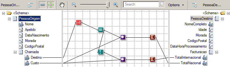
Transformations are one of the most common components in the integration processes. They act as essential translators in the decoupling between the different systems to connect. We usually associate the transformations of documents with BizTalk Server Maps, but the reality is that there are two types of transformations:
Semantic Transformations: This type of transformation usually occurs only in BizTalk maps. Here the document maintains the same represented syntax (XML) but changes its semantics (data content). This type of transformation is typically one-way since when we add and aggregate small parts of the information that compose the document into another different document, we may miss important details for its reconstruction.
Syntax Transformations: This type of transformation occurs in the receive or send pipelines and aims to transform a document into another representation, e.g., CSV to XML. Here the document maintains the same data (semantics) but changes the represented syntax. i.e., we translate the document, but typically don’t modify the structure. Usually, this type of transformation is bidirectional. Since we still have the same semantic content, we can apply the same transformation logic and obtain the document in its original format. Common examples of these transformations are also conversions between HL7 and XML or EDI and XML.
Sometimes also called Data transformation and Data translation, for that order.
This blog is an introductory note for those taking the first steps in this technology.
What are Flat Files?
One of the most ancient and common standards for message representation is using text files (Flat Files) like CSV (Comma Separated Values) or TXT files, many of which are custom-made for their systems.
However, over time, XML and, nowadays, JSON have become the standard message format because of their widespread use by major corporations and open-source development efforts. However, do not be fooled and think these messages are outdated and rarely used. A good example is EDI messages, which are used extensively by large companies, so it is often necessary to transform text files into XML and vice versa.
In the context of Microsoft BizTalk Server, a flat-file instance message is a text file that can contain three logical parts:
A header.
A body.
And a trailer.
In that order. Of course, both the header and the trailer are optional. The following example shows a flat-file instance message consisting of all three parts, with the body in bold type:
Sandro Pereira Porto, Portugal PO,1,BOOK,4415 TRANS-1
For the flat file disassembler to correctly distinguish the header, the body, and the trailer of a flat-file instance message, you must create and configure a separate schema for each of them.
Flat File Message Headers
The Flat file disassembler’s parsing of the optional flat-file instance message header is controlled by the flat file schema that you have configured in the Header schema design-time property of the flat file disassembler or the XMLNORM.HeaderSpecName message context property. If you have not specified a schema using one of these two methods, the flat file disassembler assumes that the flat file instance message does not contain a header.
For outbound flat-file instance messages, you can configure the flat file assembler to produce a header by specifying the appropriate schema in its Header Specification Name design-time property or the XMLNORM.HeaderSpecName message context property.
Data found in inbound flat-file instance message headers can be preserved and utilized in two different ways.
First, flat-file instance message headers can be saved in their entirety within the message context of the body for later restoration as the header of a corresponding outbound flat-file instance message. You can use the recipient pipeline’s Preserve header property to specify that the header should be preserved. And if a header is specified in the Flat file assembler, the preserved header will be used on the outbound message.
Second, individual data items from a flat-file instance message header can be copied to the message context associated with the flat-file message body by specifying property promotion for one or more of the fields in the corresponding schema.
Flat File Message Bodies
A flat-file instance message body, which is required, is what the Flat file disassembler processes into one or more XML instance messages. To know what data to expect in an inbound flat-file instance message body, you must configure the Flat file disassembler with the flat file schema corresponding to the body. You can specify the schema by using the Document schema design-time property of the flat file disassembler or the XMLNORM.DocumentSpecName message context property. Because flat file instance messages must have a body part, you must configure the appropriate schema using one of these two methods.
For outbound flat-file instance messages, the Flat file assembler can dynamically determine the appropriate flat-file schema for the body of the instance message. The Flat file assembler determines the appropriate schema from the message type, which is a combination of the target namespace and the root element’s name, both of which must be present in the XML version of the outbound message. Alternatively, you can explicitly configure the flat-file schema to be used by configuring the Document schema design-time property of the Fflat file assembler or the XMLNORM.DocumentSpecName message context property.
Data found in inbound flat-file instance message bodies can be copied to the corresponding message context by specifying property promotion in the flat-file schema being used by the Flat file disassembler to process the inbound instance message. Likewise, data in the message context can be copied back into outbound flat-file instance messages by specifying property demotion in the flat-file schema being used by the Flat file assembler to process the outbound message.
Flat File Message Trailers
As with flat-file instance message headers, the parsing of the optional flat-file instance message trailer by the Flat file disassembler is controlled by the flat file schema that you have configured in the Trailer schema design-time property of the flat file disassembler or the XMLNORM.TrailerSpecName message context property. If you have not specified a schema using one of these two methods, the Flat file disassembler will assume that the flat file instance message does not contain a trailer.
Unlike flat-file instance message headers, flat-file instance message trailers can neither be saved and restored as a single unit nor can they use property promotion to copy individual data items to the message context associated with the flat-file instance message body. However, a trailer can be added to an outbound flat file instance message by specifying the appropriate schema in the Trailer schema design-time property of the flat file assembler or the XMLNORM.TrailerSpecName message context property. The data that constitutes the variable portion of the trailer can be specified using property demotion from the message context of the flat-file instance message body or by specifying default or fixed values in the corresponding schema.
Flat-File Schema Types
Within a particular part of a flat-file instance message, different data items are grouped into records, which themselves can contain sub-records and, ultimately, individual data items known as fields. These records and fields are distinguished from each other using one of two different basic methodologies.
The first methodology, known as positional, defines each data item as a pre-established length, with pad characters being used to bring a shorter item of data up to its expected length.
The second methodology, known as delimited, uses one or more special characters to separate items of data from each other. This methodology avoids the need for otherwise superfluous pad characters, but introduces some special considerations when the data itself contains the character or sequence of characters being used as a delimiter.
Positional Flat Files
Positional records within a flat-file instance message contain individual fields (items of data) that are each of a predefined length. The fields are parsed according to these lengths. For example, consider the following positional record from a flat-file instance message containing an id, country code, client name, and Country name:
01 PT Sandro Pereira Portugal
A reasonable definition for this record in a flat-file schema can be described as follows:
A positional record named Client contains the following fields:
An attribute named id that is left-aligned, 3 characters in length, with a zero character offset.
An element named countryCode that is left-aligned, 3 characters in length, with a zero character offset.
An element named name that is left-aligned, 37 characters in length, with a zero character offset.
An element named country that is left-aligned, and the length is until the end of the line.
Given these record and field definitions, the Flat file disassembler will produce the following XML equivalent of this record:
    PT
    Sandro Pereira
    Portugal
There are several considerations related to positional records that will affect how the record is parsed when received and constructed when sent, including:
The character used to fill the unused portion of each field, known as the pad character.
An optional tag within the record can be used to distinguish the record from other similar records. Tags usually occur at the beginning of the record but are allowable anywhere within it. Positional records can be defined to have a tag or not have a tag, but once defined, the tag must be present or not, based on the definition.
How data is justified within a fixed length field relative to the accompanying pad characters.
Positional records nested within other positional or delimited records.
Positional records with field lengths specified as a specific number of bytes rather than a specific number of characters.
Notes:
If your flat file contains both delimited and positional records, you must set the Structure property of the root node to Delimited and the Structure property of subordinate record nodes to either Delimited or Positional as appropriate.
Fields in positional records have a limit of 50000000 characters.
Delimited Flat Files
Delimited records within a flat-file instance message contain nested records and/or individual fields (items of data) that are separated by a predefined character or set of characters. The fields are parsed according to these separating delimiters. For example, consider the following delimited records from a flat-file instance message, which contain three client lines to add to our internal system hypothetically:
A reasonable definition for this record in a flat-file schema can be described as follows:
A delimited repeating record named Client with child delimiter {CR}{LF}
And delimited elements with child delimiter ;
firstName
lastName
birthYear
city
zipCode
Given these record and field definitions, the Flat file disassembler produces the following XML equivalent of these records.
        Sandro
        Pereira
        1978
        Crestuma
        4415


   ...

...
There are several considerations related to delimited records that will affect how the record is parsed when received and constructed when sent, including:
The character or characters are used to override the interpretation of delimiters so that they are treated as part of the data.
An optional tag at the beginning of the record can be used to distinguish the record from other similar records.
How data is justified within fields with minimum lengths relative to the accompanying pad characters.
Positional records nested within other delimited records.
How data is justified within a fixed length field relative to its accompanying pad characters.
Preservation and suppression of delimiters when flat-file messages are received and sent.
Notes:
If your flat file contains both delimited and positional records, you must set the Structure property of the root node to Delimited and the Structure property of subordinate record nodes to either Delimited or Positional as appropriate.
Delimited fields in flat files have a limit of 50000000 characters.
How does the text files (Flat Files) are processed by BizTalk?
Internally, BizTalk “prefers” to use the message type XML. If messages are in XML format, BizTalk “offers” numerous automatisms that are very useful in these environments, such as message routing based on a particular field (promoted property), tracking and analysis of multidimensional values and dimensions with BAM (Business Activity Monitoring), or making logical decisions within orchestrations (business processes) using elements of the message.
If messaging is the foundation of BizTalk Server, the message schemas are the bedrock on which messaging is built. Fortunately, BizTalk supports converting text files to XML simply and intuitively using Flat File Schemas, which are simple XML schemas (XSD) with specific annotations. At first glance, this may seem strange because XML Schemas (XSD) are used to describe XML files. However, BizTalk uses them as metadata to describe XML documents and text files (flat files).
The trick is that all the necessary information, such as the delimiter symbols or the element size in a positional file, i.e., the definition of the rules of parsing (transformation rules), are embedded in the form of annotations in XML Schema (XSD), thereby simplifying the reuse of all these schemes in different parts of the process. The document can be translated back into a flat file at any point because the definition is declarative and symmetric.
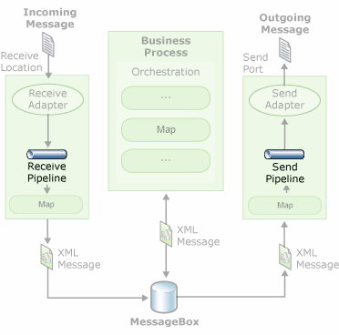
Where can syntax transformations occur?
This type of transformation – Syntax Transformations – can occur in receive or send pipelines. Usually, text files (Flat Files) are processed at runtime as follows:
The Flat Files are received by an adapter associated with a receive location (Folder in File System, for example).
A pipeline configured in the receive location will be responsible for transforming the Flat File into its equivalent XML.
One or more interested in the message, such as orchestration, will subscribe to the XML document, and this message will go through the business process. Note in a pure messaging scenario, orchestrations are unnecessary.
If and when necessary, BizTalk can send XML messages again as text files (Flat Files) by using another pipeline in the send ports, which will be responsible for transforming the XML into its equivalent, the Flat File.
As the image below shows:
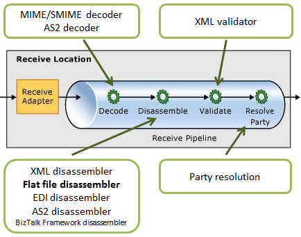
The receive pipeline consists of four stages, being that syntax transformations may occur in two of them:
Decode Stage: This stage is used for components that decode or decrypt the message. The MIME/SMIME Decoder pipeline component or a custom decoding component should be placed in this stage if the incoming messages need to be decoded from one format to another. The syntax transformations can occur in this stage through a custom component.
Disassemble Stage: This stage is used for components that parse or disassemble the message. The syntax transformations should occur at this stage. In the example that will be demonstrated in this article, we will use the “Flat file disassembler” to transform a text file into XML.
Validate Stage: This stage is used for components that validate the message format. A pipeline component processes only messages that conform to the schemas specified in that component. If a pipeline receives a message whose schema is not associated with any component in the pipeline, that message is not processed. Depending on the adapter that submits the message, the message is either suspended or an error is issued to the sender.
Resolve Party Stage: This stage is a placeholder for the Party Resolution Pipeline Component.
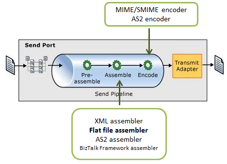
Regarding the send pipelines, they consist of three stages, being that syntax transformations may also occur in two of them:
Pre-assemble Stage: This stage is a placeholder for custom components that should perform some action on the message before the message is serialized.
Assemble Stage: Components in this stage are responsible for assembling or serializing the message and converting it to or from XML. The syntax transformations should occur at this stage.
Encode Stage: This stage is used for components that encode or encrypt the message. Place the MIME/SMIME Encoder component or a custom encoding component in this stage if message signing is required. The syntax transformations can occur in this stage through a custom component.
Hope you find this useful! So, if you liked the content or found it useful and want to help me write more content, you can buy (or help buy) my son a Star Wars Lego!
Author: Sandro Pereira
Sandro Pereira lives in Portugal and works as a consultant at DevScope. In the past years, he has been working on implementing Integration scenarios both on-premises and cloud for various clients, each with different scenarios from a technical point of view, size, and criticality, using Microsoft Azure, Microsoft BizTalk Server and different technologies like AS2, EDI, RosettaNet, SAP, TIBCO etc.
He is a regular blogger, international speaker, and technical reviewer of several BizTalk books all focused on Integration. He is also the author of the book “BizTalk Mapping Patterns & Best Practices”. He has been awarded MVP since 2011 for his contributions to the integration community.
View all posts by Sandro Pereira
String functions are used to manipulate strings in standard ways, such as conversions to all uppercase or all lowercase, string concatenation, determination of string length, white space trimming, etc. If you come from the BizTalk Server background or are migrating BizTalk Server projects, they are the equivalent of String Functoids inside BizTalk Mapper Editor.
Available Functions
The Conversion functoids are:
To DateTime: Returns the specified value as a DateTime value.
To integer: Returns the specified value as an integer.
To number: Returns the specified value as a number.
To string: Returns the specified value as a string.
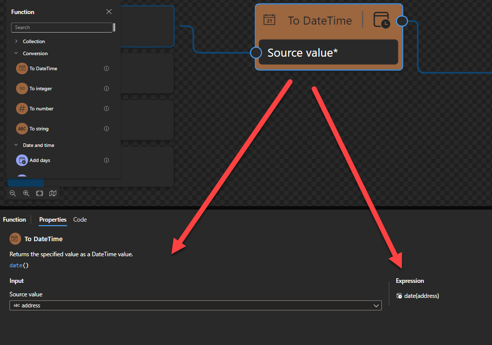
To DateTime
This function states that it returns the specified value as a DateTime value.
Behind the scenes, this function is translated to a Type casting rule in XQuery: date()
date(string?)
Rules:
Castable values are restricted by the target types implementation restrictions. For example, you cannot cast a date string with a negative year to xs:date. Such casts will result in the empty sequence if the value is provided at run time (instead of raising a run-time error).
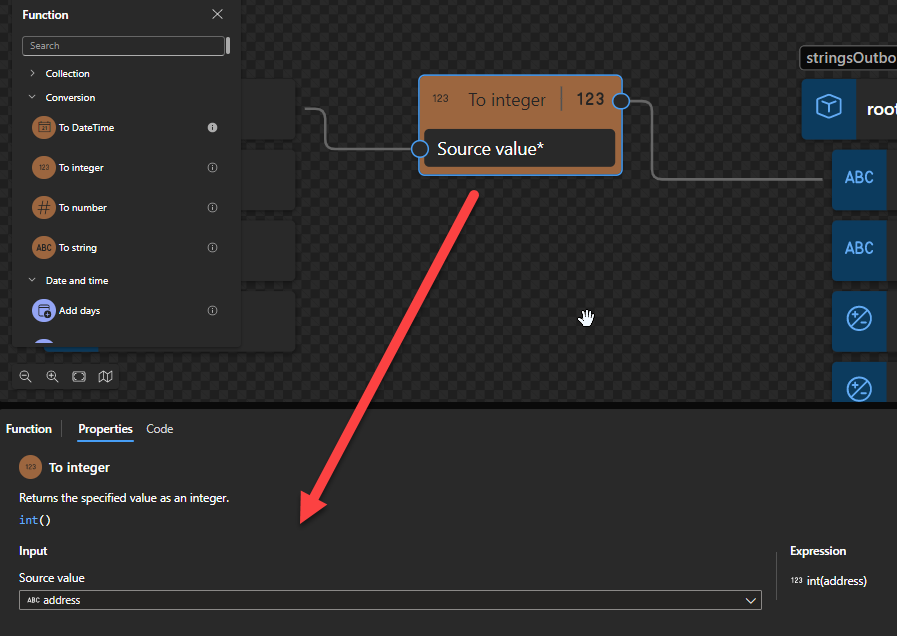
To integer
This function states that it returns the specified value as an integer.
Behind the scenes, this function is translated to the following XPath function: number()idiv 1
number($arg as xs:anyAtomicType?) as xs:doubleidiv 1
Note: idiv is an integer division operator. XPath supports two division operators named div and idiv. Each of these operators accepts two operands of any numeric type. $arg1 idiv $arg2 is equivalent to ($arg1 div $arg2) cast as xs:integer? except for error cases.
Rules:
If $arg is the empty sequence, or if $arg cannot be converted to an xs:double, the xs:double value NaN is returned.
Otherwise, $arg is converted to an xs:double following the rules of casting to xs:double. If the conversion to xs:double fails, the xs:double value NaN is returned.
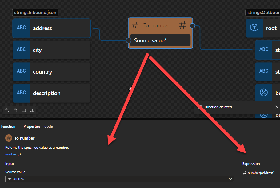
To number
This function states that it returns the specified value as a number.
Behind the scenes, this function is translated to the following XPath function:: number()
number($arg as xs:anyAtomicType?) as xs:double
Rules:
If $arg is the empty sequence, or if $arg cannot be converted to an xs:double, the xs:double value NaN is returned.
Otherwise, $arg is converted to an xs:double following the rules of casting to xs:double. If the conversion to xs:double fails, the xs:double value NaN is returned.
To string
This function states that it returns the specified value as a string.
Behind the scenes, this function is translated to a Type casting rule in XQuery: string()
string string(object?)
Rules:
A node-set is converted to a string by returning the string-value of the node in the node-set that is first in document order. If the node-set is empty, an empty string is returned.
A number is converted to a string as follows
NaN is converted to the string NaN
positive zero is converted to the string 0
negative zero is converted to the string 0
positive infinity is converted to the string Infinity
negative infinity is converted to the string -Infinity
if the number is an integer, the number is represented in decimal form as a Number with no decimal point and no leading zeros, preceded by a minus sign (-) if the number is negative
otherwise, the number is represented in decimal form as a Number including a decimal point with at least one digit before the decimal point and at least one digit after the decimal point, preceded by a minus sign (-) if the number is negative; there must be no leading zeros before the decimal point apart possibly from the one required digit immediately before the decimal point; beyond the one required digit after the decimal point there must be as many, but only as many, more digits as are needed to uniquely distinguish the number from all other IEEE 754 numeric values.
The boolean false value is converted to the string false. The boolean true value is converted to the string true.
An object of a type other than the four basic types is converted to a string in a way that is dependent on that type.
Hope you find this helpful! So, if you liked the content or found it useful and want to help me write more, you can buy (or help buy) my son a Star Wars Lego!
Author: Sandro Pereira
Sandro Pereira lives in Portugal and works as a consultant at DevScope. In the past years, he has been working on implementing Integration scenarios both on-premises and cloud for various clients, each with different scenarios from a technical point of view, size, and criticality, using Microsoft Azure, Microsoft BizTalk Server and different technologies like AS2, EDI, RosettaNet, SAP, TIBCO etc.
He is a regular blogger, international speaker, and technical reviewer of several BizTalk books all focused on Integration. He is also the author of the book “BizTalk Mapping Patterns & Best Practices”. He has been awarded MVP since 2011 for his contributions to the integration community.
View all posts by Sandro Pereira
Welcome again to another BizTalk Server Best Practices, Tips, and Tricks blog post! In my previous blog posts, I discussed some essential tips and tricks for BizTalk Server administrators:
And for BizTalk Server Developers:
Today we are going to switch and speak about another critical Best practice, Tips, and Tricks, this time for BizTalk Server developers: Orchestration Designer Shortcut Keys
#18 Orchestration Designer Shortcut Keys
The Orchestration Designer design surface provides full accessibility using the keyboard. This accessibility begins when you open the design surface, which you can do in Visual Studio by selecting menu options starting with the New option on the Filemenu.
Accessibility is also supported within the design surface, where, for example, you can select different shapes and parts of shapes by pressing the Up and Down arrows. When a shape is selected on the design surface, it is highlighted on the design surface and in the Orchestration View window (if applicable). At the same time, the Properties grid also displays information about the selected shape.
Orchestration Designer supports accessibility by providing many shortcut keys. Different shortcut keys are available depending on what part of the design surface you use.
You can also use many of the existing shortcuts available in Visual Studio, for example, when you are using Microsoft IntelliSense in the BizTalk Expression Editor.
Shortcut Keys General to the Design Surface
Key
Effect
TAB
Moves the selection and focus to the shape with inactive selection in the next design surface area on the right (the Process Area or Port Surface). Example: Selection and focus are currently on a port in the left Port Surface. When the TAB key is pressed, selection and focus move to the shape with an inactive focus in the Process Area.
SHIFT + TAB
Same as TAB, but in the opposite direction.
PAGE DOWN
Scrolls the page down so that later parts of the orchestration are shown. Selection and focus do not change.
PAGE UP
Same as the PAGE DOWN key, but in the opposite direction. Selection and focus do not change.
SHIFT + PAGE DOWN
Horizontally scrolls the entire design surface to the left by set increments. Selection and focus do not change.
SHIFT + PAGE UP
Same as SHIFT + PAGE DOWN except that the design surface scrolls to the right. Selection and focus do not change.
ENTER
Performs the default action for the selection, which usually means shifting focus to the Properties grid.
SPACE
Selects the shape that currently has the focus. There is no effect if the focus is on a shape connector.
CTRL + SHIFT + F1
Toggles between expansion and collapse of the Smart Tag of a selected shape. UP and DOWN ARROW can then be used to move through the items of a Smart Tag. When expanded, the Enter or Space keys execute the related action of a Smart Tag item (as well as collapsing the Smart Tag).
DELETE
Deletes the current selection.
Shortcut Keys Specific to the Process Area
Key
Effect
DOWN ARROW
Moves the selection to the next connecting line or shape below. If the shape is connected to several branches below (as in the case of a Decide shape), the selection moves to the first shape in the leftmost branch. If selection is on the End shape for the orchestration, pressing this key has no effect because there are no more shapes below it. If selection is on the Return shape within a branch of a complex shape, the next shape is the endpoint of the complex shape.
UP ARROW
Moves the selection to the next connecting line or shape above. If the shape is connected to several branches above, the selection moves to the last shape on the leftmost branch (even if the last shape of the branch is a Return shape). Pressing this key has no effect when the Start shape is selected.
LEFT ARROW
If the selection is on a Send or Receive shape and the shape is connected to a port: If the shape has a port connector leading to a port in the Left Port Surface, focus and selection shift to the port connector of the shape. If the shape has a port connector leading to a port in the Right Port Surface, pressing this key has no effect. If the shape has no port connector, navigation is the same as with any other shape. For other shapes (or Send or Receive shapes not connected to a port): If the selection is in a branch, and a branch exists with shapes on it to the left of the current branch, the selection moves to the nearest shape on the branch to the left. The key has no effect anywhere else in the orchestration.
RIGHT ARROW
Same as the LEFT ARROW key, but in the opposite direction.
HOME
The selection changes to the connector that leads from the Start shape of the orchestration.
END
The selection changes to the connector, leading to the orchestration’s End shape.
NUM LOCK + –
Collapses the selected complex shape.
NUM LOCK + +
Expands the selected complex shape.
NUM LOCK + *
Expands the selected complex shape, plus any child complex shapes it may have.
Shortcut Keys Specific to the Port Surfaces
Key
Effect
DOWN ARROW
If a Role Link has the focus, it shifts to the first port inside. If no ports are inside the Role Link, the focus shifts to the next port or Role Link below it. If a port has the focus, it shifts to the next port or operation below it. If an operation has the focus, it shifts to its first operation part. For the template, the focus shifts to the next port. If an operation part has the focus, it shifts to the next operation part, operation, or port below it. There is no effect if no more objects exist below the current one.
UP ARROW
Same as the DOWN key, but in the opposite direction. There is no effect if no more objects exist above the current one.
RIGHT ARROW
Left Port Surface: If an operation part has the focus, it goes to the first port connector leading out of it. If there are no connections on the current operation part, pressing this key has no effect. If an operation has the focus, the focus goes to the first port connector of the operation’s first part that has a connection. If there are no connections in the operation, pressing this key has no effect. If a port connector gets the focus, whatever was selected in the Port Surface receives inactive selection. Right Port Surface: No effect.
LEFT ARROW
Same as the RIGHT ARROW key, except in the opposite directions (that is, no effect for the left Port Surface, and the focus can go onto a port connector for the right Port Surface).
HOME
Focus and selection shift to the first shape in the channel.
END
Focus and selection shift to the last shape in the channel.
Shortcut Keys Specific to Port Connectors
Key
Effect
RIGHT ARROW
Port connectors leading to the Left Port Surface: Focus and selection shift to the connecting Send or Receive shape. The port connector is deselected. Port connectors leading to the Right Port Surface: Focus and selection shift to the connecting operation part. In this case, whatever has a selection in the Process Area now receives an inactive selection.
LEFT ARROW
Same as the RIGHT ARROW key, except directions are reversed.
DOWN ARROW
Focus and selection shift to the port connector on the next operation part. If the last connector on the last port has focus, pressing this key has no effect.
UP ARROW
Same as the DOWN ARROW key, except in the opposite direction. If the first connector has focus, pressing this key has no effect.
HOME
Focus shifts to the shape connector leading out of the Start shape.
END
The focus shifts to the shape connector leading into the End shape.
DELETE
The port connector is deleted. This clears the Port Operation property on the Send or Receive shape. Focus shifts to the affected Send or Receive shape.
I hope you enjoy this developer tip and stay tuned for the following BizTalk Server Best practices, Tips, and Tricks.
Author: Sandro Pereira
Sandro Pereira lives in Portugal and works as a consultant at DevScope. In the past years, he has been working on implementing Integration scenarios both on-premises and cloud for various clients, each with different scenarios from a technical point of view, size, and criticality, using Microsoft Azure, Microsoft BizTalk Server and different technologies like AS2, EDI, RosettaNet, SAP, TIBCO etc.
He is a regular blogger, international speaker, and technical reviewer of several BizTalk books all focused on Integration. He is also the author of the book “BizTalk Mapping Patterns & Best Practices”. He has been awarded MVP since 2011 for his contributions to the integration community.
View all posts by Sandro Pereira
In our Integration projects, especially nowadays on Azure Integration Services, we often work with JSON messages. And despite Logic App Designer allowing us to generate a JSON schema based on a JSON payload (or JSON message), there are many situations that we find ourselves in the need to create a JSON Schema outside the Logic App. One good example is when we are creating a map inside the new Data Mapper.
Unfortunately, there aren’t any out-of-the-box capabilities inside the new Data Mapper to generate a JSON Schema from a JSON Message, so we only have two options:
Create a dummy Logic App to generate the JSON Schema and then manually copy it and save in the Artifacts folder;
Or we will use free online tools like this one: https://www.liquid-technologies.com/online-json-to-schema-converter, but what annoys me about these online tools is that all data are stored in their log files, and sometimes for privacy/security concerns that can be a problem.
Mainly because of these reasons, I decide, along with my team, to start creating these free tools with the source code available on GitHub in order to not raise the same suspicions.
JSON Document to JSON Schema Converter Tool
JSON Document to JSON Schema Converter Tool is a straightforward Windows that allows you to generate a JSON Schema based on the sample JSON Document that we provide. No data are stored in log files.
Where can I download
Hope you find this useful! So, if you liked the content or found it useful and want to help me write more content, you can buy (or help buy) my son a Star Wars Lego!
Credits
Luis Rigueira | Member of my team and one of the persons responsible for developing this tool.
Author: Sandro Pereira
Sandro Pereira lives in Portugal and works as a consultant at DevScope. In the past years, he has been working on implementing Integration scenarios both on-premises and cloud for various clients, each with different scenarios from a technical point of view, size, and criticality, using Microsoft Azure, Microsoft BizTalk Server and different technologies like AS2, EDI, RosettaNet, SAP, TIBCO etc.
He is a regular blogger, international speaker, and technical reviewer of several BizTalk books all focused on Integration. He is also the author of the book “BizTalk Mapping Patterns & Best Practices”. He has been awarded MVP since 2011 for his contributions to the integration community.
View all posts by Sandro Pereira
In our Integration projects, especially nowadays on Azure Integration Services, we often work with JSON messages. And despite Logic App Designer allowing us to generate a JSON schema based on a JSON payload (or JSON message), but there are many situations we need the opposite! We want to generate a dummy message from the JSON Schema in order to test our Logic Apps solutions or now our Data Mapper maps.
Unfortunately, there aren’t any out-of-the-box capabilities inside Logic Apps or the new Data Mapper to generate a dummy message.
I’m doing a lot of demos and sessions on the new Data Mapper, and you cannot imagine the times I forget what the input message for each specific map is, and I find myself always looking for that information.
In order to accomplish that, we normally use free online tools like this one: https://www.liquid-technologies.com/online-schema-to-json-converter, but what annoys me about these online tools is that all data are stored in their log files, and sometimes for privacy/security concerns that can be a problem. Mainly because of this reason, I decide, along with my team to start creating these free tools with the source code available on GitHub in order to not raise the same suspicions.
Create a sample JSON document from a JSON Schema Tool
Create a sample JSON document from a JSON Schema Tool is a straightforward Windows tool that allows you to create a JSON Document based on the JSON Schema that we provide. No data are stored in log files.
Download
Hope you find this useful! So, if you liked the content or found it useful and want to help me write more content, you can buy (or help buy) my son a Star Wars Lego!
Credits
Luis Rigueira | Member of my team and one of the persons responsible for developing this tool.
Author: Sandro Pereira
Sandro Pereira lives in Portugal and works as a consultant at DevScope. In the past years, he has been working on implementing Integration scenarios both on-premises and cloud for various clients, each with different scenarios from a technical point of view, size, and criticality, using Microsoft Azure, Microsoft BizTalk Server and different technologies like AS2, EDI, RosettaNet, SAP, TIBCO etc.
He is a regular blogger, international speaker, and technical reviewer of several BizTalk books all focused on Integration. He is also the author of the book “BizTalk Mapping Patterns & Best Practices”. He has been awarded MVP since 2011 for his contributions to the integration community.
View all posts by Sandro Pereira
In a general and abstract way, we can say that Data Mapper maps are graphical representations of XSLT 3.0 (Extensible Stylesheet Language Transformation) documents that allow us to perform simple and visual transformations between XML and JSON messages (more formats will be added in the future). But in reality, Data Mapper maps are composed of two files: a Map Definition file (.yml) that basically is an abstraction of the underlying implementation. And one XSLT file (.xslt) contains all the transformation rules – This is the file that in runtime will be executed by the Logic Apps (standard) engine.
What types of transformation can we apply in Logic Apps?
Similar to BizTalk Server, we can define two types of transformations:
Syntax Transformations: In BizTalk Server, this type of transformation occurs in receive or send pipelines and aims to transform a document into another representation, e.g., CSV to XML. In Logic Apps, that will occur inside the Logic Apps by using an Integration Account or certain actions and expressions depending on which syntax transformation we need to perform. Here the document maintains the same data (semantics) but changes the syntax that is represented. I.e., we translate the document, but typically we don’t modify the structure. Normally, this type of transformation is bidirectional, since we still have the same semantic content, we can apply the same transformation logic and obtain the document in its original format.
Semantic Transformations: In BizTalk Server, this type of transformation usually occurs only in BizTalk maps. Inside Logic Apps (Standard), they will take place in the Data Mapper. Here the document can maintain the same syntax that is represented (XML or JSON) – not mandatory since Data Mapper supports at the moment JSON Schemas and XML Schemas – but changes its semantics (data content). These types of transformations are typically one-way. Since we add and aggregate small parts of the information that compose the document into another document, we may miss important details for its reconstruction.
Introduction to the Data Mapper
The Data Mapper enables us to perform transformations of complex messages visually and effortlessly, graphically represented by links that define the relationships between the various elements of messages.
These relationships between elements are internally implemented as XSL Transformations (XSLT – Extensible Stylesheet Language Transformation), the standard Worldwide Web Consortium (W3C) recommended to perform message transformations.
Data Mapper is a Visual Code extension that allows you to perform mapping transformations. Currently, it has its own extension, but that will be merged with the main extension in the future.
Essentially the editor consists of three main modules:
Source Schema view: this is the data structure of the source message and is on the left side of the main window;
Destination Schema view: this is the data structure of the target message and is on the right side of the main window; the links that define the mapping lead into the destination schema tree view from the grid view, and ultimately from the source schema tree view.
Mapping areaview: is in the middle of the main window, between the two data structures (source and target); This area plays a critical role in the definition of maps, containing the links and Functions that control how data in a source instance message is transformed into an instance message that conforms to the destination schema. The mapping area can have multiple layers, each of them associated with a specific record on the destination schema, allowing us this way to organize complex maps in a better way.
Apart from these three modules, there are other important windows for the developer:
Function panel: At the left side of the source schema, providing access to all Functions we can use in the Data Mapper.
Function properties panel: in this panel, we can see and modify the properties of a selected function inside the Data Mapper.
Task List and Output windows: much of the time hidden, we can and must use these windows to examine the results of saving and testing we do in our maps. These windows normally appear underneath the Mapping area or the Function properties panel.
Code view Panel: On this panel, you can view Map definitions rules (abstraction of the underlying implementation). It is a read-only panel.
Basic maps functionalities (Document mapping)
There are several mapping functionalities that you can perform inside maps, like Data normalization, Transform Injection (XLST injection), calculating values covering math and scientific functoids, and so on. Still, most of the time, transformations are quite simple, and when we perform a transformation in the message 5 basic functionalities typically arise:
Simple mapping of a given value (direct copy)
Concatenation of values
Conditional selection
Custom scripts
Add new values (data)
Here we will take a simple transformation problem that will address each one of these functionalities or operations, providing a simple example of how to accomplish this inside the Data Mapper. Of course, there are plenty of other operations or transformation rules that we could do that will not be addressed here.
Hope you find this helpful! So, if you liked the content or found it useful and want to help me write more content, you can buy (or help buy) my son a Star Wars Lego!
Author: Sandro Pereira
Sandro Pereira lives in Portugal and works as a consultant at DevScope. In the past years, he has been working on implementing Integration scenarios both on-premises and cloud for various clients, each with different scenarios from a technical point of view, size, and criticality, using Microsoft Azure, Microsoft BizTalk Server and different technologies like AS2, EDI, RosettaNet, SAP, TIBCO etc.
He is a regular blogger, international speaker, and technical reviewer of several BizTalk books all focused on Integration. He is also the author of the book “BizTalk Mapping Patterns & Best Practices”. He has been awarded MVP since 2011 for his contributions to the integration community.
View all posts by Sandro Pereira